


Y1-03-0250 Rev. B 19
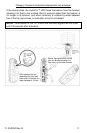
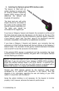
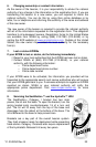
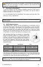
5. Installing the Optional optical GPS interface cable
The beacon is fitted with an
optical interface to connect with
an external Global Positioning
System (GPS) receiver that will
determine the latitude and
longitude of its position.
The black lead wire with white
stripes should be connected to
the output of the external GPS
receiver positive transmitter pin.
The black wire should be
connected to the negative pin.
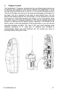
If you have a Category I beacon and bracket, the connector is at the end of
the black lead wire plugs into the beacon via the bezel on the top of the
beacon. See the location of the GPS interface in previous figures (“Anatomy
of your beacon”, page 7 and “Top View”, page 8). It is important to seat the
connector completely in the bezel for an operational connection.
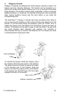
If you have a Category II beacon and bracket, your connector has two
extensions on it that must be aligned with the two notches on the Category II
beacon bezel. The connector is then gently inserted downward into place
and turned 90° to lock the connector into the bezel.
If the external GPS receiver is operational and the connection has been
correctly made to the optical interface, the green LED in the optical interface
will start flashing at activation.
NOTE:
The baud rate output for your GPS receiver NMEA 0183 should be
4800 bps. If you are not sure if your receiver is NMEA 0183 compliant,
check the interface settings listed in your GPS manual. To optimize your
GPS interface feature, be sure that your GPS receiver is equipped with a
NMEA 0183 Version 1.5 or higher with GPGGA sentence enabled.
Consult your GPS receiver manual for the maximum cable length
acceptable for an external GPS connection to the beacon. Also see
Appendix A for information regarding the use and testing of your GPS
system in conjunction with the beacon.
Using the optical interface is not necessary for the beacon to function
properly; it will, however, enhance the beacon’s performance.