


21
Y1-03-0222 Rev. C
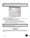
If the red LED illuminates continuously, the unit should be assumed to be faulty. It should either be switched off
(power removed) or, if this is not practical, any other vessel position information derived from the unit should not
be used. It should also be assumed that the unit is not transmitting valid position information for your vessel.
The unit should be examined by a competent equipment maintainer at the earliest opportunity.
More details on LED indications can be found in “LED Indicators” (below).
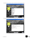
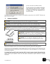
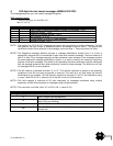
3. Data port messages
The data port will output the following:
(At power-up) boot-loader and main application splash text screens including version numbers, and
memory status
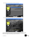
Details of relevant AIS transmissions received
Details of AIS transmissions sent
Details of channel management messages received
Alarm messages generated by the BIIT function
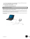
The data port will accept the following inputs:
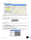
Programming information
Alarm acknowledgements
Please see the ‘Data Interface’ section of this manual for more details of the data port messages.
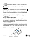
When in operation, an AIS unit:
Uses one of two VHF channels within the international marine band allocation (channel 87B;
161.975MHz, or channel 88B; 162.025MHz) to regularly transmit information such as the vessel
position, Maritime Mobile Service Identity (MMSI), name, speed, course, etc.
Receives similar information from other AIS equipped vessels within VHF range and outputs that
information for use by an external display medium (AIS enabled chart plotter, PC using AIS enabled
chart plotter software etc.)
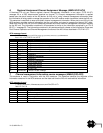
4. Built-in test
The Nauticast™-B AIS unit is equipped with Built in Integrity Testing (BIIT). BIIT tests run continuously or at
appropriate intervals simultaneously with the standard functions of the equipment. The BIIT detects any failure
or malfunction that will significantly reduce integrity or stop operation of the Nauticast™-B AIS unit.
The tests include:
AIS TX malfunction (synthesizer not locked and TX time-out not exceeded)
Antenna VSWR exceeds limit
Rx channel 1 malfunction (synthesizer not locked)
Rx channel 2 malfunction (synthesizer not locked)
Internal GNSS not in use
No valid SOG information
No valid COG information
Background noise > -77dBm
GPS failure
VSWR exceeding the maximum allowed level
The input voltage is out of the specified range
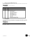
5. LED indicators
Power
This is a green LED which indicates, when lit, that power has been connected correctly to the transponder, that
the transponder hardware has been configured, that the operating software is present, that the CPU has booted
up and the application software is running.