


22
Y1-03-0222 Rev. C
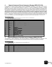
TX timeout
This is a yellow LED which indicates when lit that the CSTDMA transmitter is prevented from transmitting.
Reasons for this include the following:
The transponder‟s internal GPS receiver is not yet ready. The yellow LED will go out and the green LED
will light when GPS receiver is ready.
The transponder was unable to transmit an AIS message due to the channel being already occupied,
e.g. by transmissions from other AIS transponders. Wait 10 minutes and verify GPS antenna
connection.
The transponder‟s internal GPS receiver is not operating. Contact your local dealer for service.
Error
This is a red LED which indicates, when lit, one of the following status conditions is possible:
Transmitter lockout timer (1 second maximum) has operated
GPS is unable to gain lock after 30 minutes
VHF antenna VSWR is out of range
Power Supply is out of range
Background noise level is above the threshold level (-77dBm)
MMSI is not entered
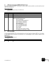
Blue LED
The unit has a blue LED that, when lit, indicates one of the following two conditions depending on how it is
programmed:
Safety Related Message (SRM) status
The Safety Related Message (SRM) button (not included, recommend momentary contact switch rated
for > 25mA) has been depressed for more than 2 seconds and the pre-set SRM has been sent. If the
SRM LED is illuminated it is not possible to send another SRM. An SRM can be sent once a minute.
The payload within the message 14 transmission is the text string “MAYDAY MAYDAY”.
Silent Mode Function (if user configures SRM switch to act as Silent Mode switch)
This indicates that the Silent Mode button has been depressed for more than 2 seconds and the pre-set
Silent Mode has been activated. If the blue LED is illuminated you are not transmitting your AIS data to
other vessels, your AIS is acting as a receive-only device. Depress the Silent Mode button a second
time transmit your position data.
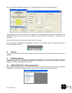
Both of these functions can be accessed through the Link2AIS™ software when a switch is not installed.
SECTION 4 - MAINTENANCE
WARNING:
Unauthorized opening of the Nauticast™-B AIS system will invalidate the warranty.
CAUTION:
Avoid using chemical solvents to clean the Nauticast™-B AIS as some solvents can damage the
case material. To clean, wipe down with a damp cloth.
NOTE:
The Nauticast™-B AIS contains no user serviceable parts. Contact your Service Agent for repair.
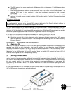
APPENDIX A - SERIAL DATA INTERFACE
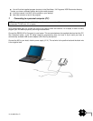
1. Power/ Data connection
There is a 15-pin D-Sub female connector mounted on the side of the transponder case. The standard
data/power cable assembly provided mates with this connector.
NOTE:
Both thumb screws on the power/data cable will be tightened securely.
Power
12V DC (9.6-15.6V) is connected to the transponder power supply input via the data/power cable. The red wire
is the positive lead and the black wire is the negative lead.