


C
D
E
B
A
3500 Series Stainless
Steel 1NM and 2NM
Vertical Mount Sidelights
LED Sidelight Pair: 3560 / 3570
1NM SIDELIGHTS (SERIES 3560)
For boats up to 12 meters / 39.4 feet. Meets USCG CFR 183.810, ABYC A-16
requirements and all applicable standards as tested by Imanna Laboratories, on
4/25/2008. 1 nautical mile visibility.
2NM SIDELIGHTS (SERIES 3570)
For boats up to 50 meters / 164 feet. Meets USCG CFR 183.810, ABYC A-16
requirements and all applicable standards as tested by Imanna Laboratories, on
5/9/2008. 2 nautical mile visibility.
REQUIRED FOR INSTALLATION
• Phillips screwdriver
• Drill and bits: 3/8" (10mm) for wire clearance hole and 1/8" (3mm) for mounting holes
• Pilot 1/8" (3mm) drill for mounting screws
• Two #8 pan head stainless steel screws (not included)
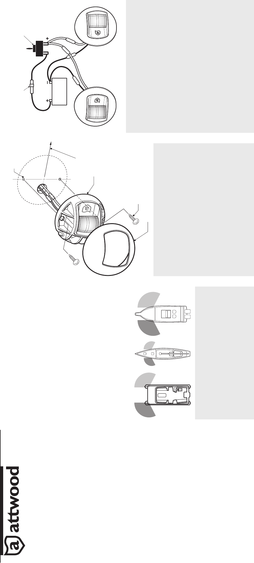
LOCATION
1. Before drilling mounting hole, position sidelights on a surface of the gunwale or
deck where you are certain that sidelights:
• Are equal distance from the bow (Figure 1)
• Shine straight ahead
• Shine within a 5° of horizontal when the boat is fl oating
• The light beam is not obstructed
2. Place lights with the light labeled red on the port (left) and the light labeled green
on the starboard (right). Be sure there are no obstructions at the front or side
within the light’s arc of visibility (112.5° each side).
3. Measure and mark location of wire clearance hole. At the marked location(s),
make a mark for a 3/8” hole. (Figure 2).
• Both mounting holes must be the same distance from the bow.
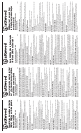
DRILLING INSTRUCTIONS
1. Remove the cover. (Figure 2).
2. Align hole beneath light base with the position you’ve marked for the wire
clearance hole. Set the lamp toward the bow.
3. Use the light base as a template to mark locations for the mounting screw pilot
holes (use two #8 stainless steel screws).
CAUTION
Position holes carefully on aluminum boats so that wires do not contact the hull.
4. Drill wire clearance hole and pilot holes for the mounting screws.
MOUNTING INSTRUCTIONS
1. Feed wires through the hole in the deck.
2. Insert two #8 stainless steel mounting screws through base and fasten base to
the deck.
3. Snap stainless steel cover mounting base.
NOTE: If area below the light will not be reachable after installation, attach a suitable
length of 16-gauge red- and black-colored NON-POWERED wire that can be routed
to an accessible area. Make connections according to WIRING INSTRUCTIONS below.
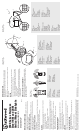
WIRING INSTRUCTIONS
The power supply must be 12-volt DC ONLY. Use crimp-type marine-grade
connectors with suitable waterproof insulation. Protect all connections with
suitable materials.
NOTE: Failure to make proper connections and fuse the light properly will void the
product warranty.
CAUTION
Polarity is important. If wiring is mis-connected the LED light will not operate.
1. Connect wires to fused power source: (See Figure 3).
• Connect the (-) black wire to the negative (-) wire from the 12-volt supply.
• Connect the (+) gray or red wire along with proper fuse and switch to the
positive (+) 12-volt supply.
• Fuse must be 1-amp.
2. Note that navigation rules require sidelights to be operated separately from
anchor lights. Use either two switches or a single switch with three positions
for off/anchor/running.
ATTWOOD LIMITED 10-YEAR WARRANTY
Because of the longevity of Attwood’s LED lighting technology, Attwood offers
a limited 10-year warranty on this LED lighting product. See Product Catalog or
attwoodmarine.com for details.
SAVE THESE INSTRUCTIONS
Form Number 69440 Rev. A 08-05
© 2008 Attwood Corporation
1016 N. Monroe Street, Lowell, MI 49331-0260 www.attwoodmarine.com
Figure 1 / Figura 1
Abbildung 1 / Figur 1
Figure 2
A. Red (Port)
B. Green (Starboard)
Figure 2
A. Rouge (bâbord)
B. Vert (tribord)
Figura 2
A. Rojo (babor)
B. Verde (estribor)
Abbildung 2
A. Rot (Backbord)
B. Grün (Steuerbord)
Figur 2
A. Röd (babord)
B. Grön (styrbord)
BA
Figure 2 / Figura 2
Abbildung 2 / Figur 2
Figure 3
A. Pilot Holes
B. Bow Direction
C. Base
D. Mounting Screw
E. Lens Cover
Figure 3
A. Trous de guidage
B. Direction de la proue
C. Base
D. Vis de montage
E. Couvercle de la lentille
Figura 3
A. Agujeros guía
B. Dirección a la proa
C. Base
D. Tornillo de montaje
E. Tapa de la lente
Abbildung 3
A. Führungslöcher
B. Bugrichtung
C. Sockel
D. Montageschrauben
E. Linsenabdeckung
Figur 3
A. Styrhål
B. Stävriktning
C. Fäste
D. Monteringsskruv
E. Linshölje
Figure 3 / Figura 3
Abbildung 3 / Figur 3
Figure 3
A. 1-Amp Fuse
B. Switch
C. (pos)
D. (neg)
E. 12 V DC
F. Green (Starboard)
G. Red (Port)
Figure 3
A. Fusible d’un ampère
B. Interrupteur
C. (pos.)
D. (nég.)
E. 12 volts CC
F. Vert (tribord)
G. Rouge (bâbord)
Figura 3
A. Fusible de 1 amperio
B. Interruptor
C. (positivo)
D. (negativo)
E. 12 V de CC
F. Verde (estribor)
G. Rojo (babor)
Abbildung 3
A. Sicherung 1 A
B. Schalter
C. (pos.)
D. (neg.)
E. 12 V Gleichstrom (DC)
F. Grün (Steuerbord)
G. Rot (Backbord)
Figur 3
A. 1 A-säkring
B. Brytare
C. (pos)
D. (neg)
E. 12 V DC
F. Grön (styrbord)
G. Röd (babord)
C
D
C
E
G
B
A
F