


3
®
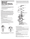
3800 Series Stainless
Steel 2-Mile Sidelights
Bicolor Combination Bow Light: 3810
Sidelight Pair: 3820
Attwood marine hardware, navigational lighting, bilge pumps, and other
marine accessories are specified more than any other brand by America’s
best-known boat manufacturers as original equipment. Look to Attwood
for quality replacement parts and marine accessories.
SAVE THESE INSTRUCTIONS
Form Number 69360 Rev. A 00-01
Red
(Port)
Green
(Starboard)
Red
(Port)
Green
(Starboard)
FEATURES
The Attwood Stainless Steel sidelights provide 2-mile visibility
with advanced optics for greater visibility and safety. The housing
is corrosion-proof with an aerodynamic design for an attractive
appearance on the deck of your boat. The base gasket forms a
seal between the lens and deck for an easy, waterproof installation.
Side reflectors provide added protection even when the light is not
on. These lights exceed all requirements of ABYC A-16-97 and
COLREG 72 for boats up to 20 meters/65.6 feet (BiColor Bow
Light 3810) and up to 50 meters/164 feet (Sidelight Pair 3820).
REQUIRED FOR INSTALLATION
• Phillips screwdriver
• Drills: ³⁄₄" for wire clearance hole
Pilot drill for mounting screws
• Two #10 pan head stainless steel screws (not included)
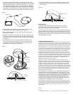
LOCATION
1.Position light(s) on a surface of the gunwale or deck that is
horizontal (within +/-5 degrees).
2.When installing bicolor combination light, place it on the
centerline of the boat at the bow (See Figure 1a).
When installing sidelight pairs, place lights with the red lens
on the port (left) and green lens on the starboard (right) as you
stand onboard facing bow of the boat. Lights must be parallel
to centerline of the boat (See Figure 1b).
Figure 1a Figure 1b
3.Make sure there are no obstructions at the front or side such as
rail stanchions, chocks, anchors, cleats, etc. within the light’s arc
of visibility (112.5 degrees each side).
4.Measure and mark location of wire clearance hole. If installing a
bicolor light, location must be on the boat centerline. If installing
a sidelight pair, both must be the same distance from the bow.
At the marked location(s), make a mark for a ³⁄₄" hole. This hole is
necessary for wire passage and lamp ventilation (See Figure 2).
Figure 2
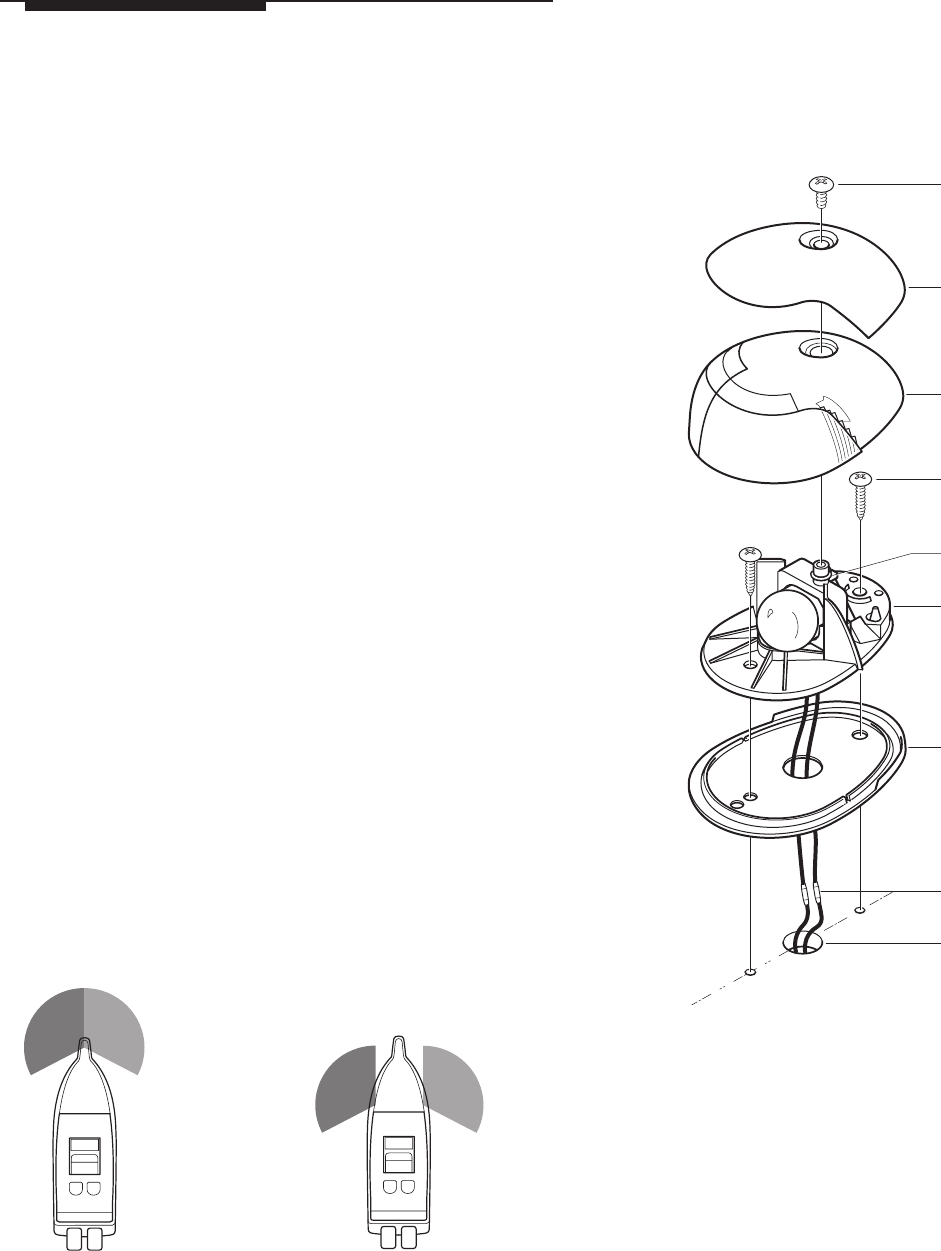
MOUNTING INSTRUCTIONS
1.Remove the cover and lens by removing the Phillips head screw
in the cover and lifting off (See Figure 2).
2.Align hole beneath light base with the position you’ve marked for
the clearance hole. Set lens toward the bow and align arrow on
base with the boat centerline. Use the light base as a template
to mark locations for the mounting screw pilot holes (use at least
2 #10 stainless steel screws).
CAUTION:
Position holes carefully on aluminum boats so that wires do not
contact the hull.
3.Drill clearance hole and pilot holes for the mounting screws.
WIRING INSTRUCTIONS
The power supply must be 12-volt DC ONLY. Use crimp type
marine-grade connectors with suitable insulation. Protect all
connections with suitable materials.
NOTE:
Failure to make proper connections and fuse the light properly (see
back page) will void the product warranty.
3/4" Hole Aligned
with Boat Centerline
Gasket
Butt-Joint
Connectors
Cover Screw
Lens Cover
Lens
Base
O-Ring
#10 Stainless Steel
Mounting Screws
•
•
•
•
•
•
•
•
•