


Locked
Verrouillé
Trabado
Unlocked
Déverrouillé
Destrabado
Horizontal Mount
Montage horizontal
Montaje horizontal
Optional
Adaptor
Adaptateur
en option
Adaptador
opcional
Vertical Mount
Montage vertical
Montaje vertical
Locked
Verrouillé
Trabado
Unlocked
Déverrouillé
Destrabado
Optional
Adaptor
Adaptateur
en option
Adaptador
opcional
One meter
or 39-3/8"
39 3/8 po
(un mètre)
39-3/8"
(un metro)
All-Round Light
5550 Series LED Anti-Glare Fold-Down
and Fixed Base Lights
Installation Instructions
SAVE THESE INSTRUCTIONS
Form Number 69428 Rev. A 07-10
© 2007 Attwood Corporation
1016 N. Monroe Street, Lowell, MI 49331-0260 www.attwoodmarine.com
Lights meet USCG CFR 183.810, ABYC A-16 requirements, and all applicable standards
as tested by Immana Labs, 5/3/07. 2 Nautical Mile visibility.
CAUTION: Read all instructions carefully before installing and using this product. All positive
(+12V DC) lighting wires require a 1-amp fuse to protect circuits and vessel. The aluminum
light pole is not grounded. MAKE SURE POWER SOURCE IS 12-VOLT DC ONLY. HIGHER
VOLTAGE WILL DAMAGE LIGHT AND CIRCUITRY.
WARNING
To prevent injury, disconnect power when installing or servicing this product. Remove
boat from water before using 120V power tools.
REQUIRED FOR INSTALLATION
• Cordless drill; 1/8" and 3/8" (3 and 10mm) bits
• Marine-grade non-silicone sealant
• Phillips screwdriver
• Two #10 pan head stainless steel screws
• 3-position switch (OFF/ON/ON)
• Fuse holder and fuse: 1-amp
• 16-gauge wire
• Appropriate marine-grade wire connectors
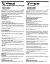
LED Anti-Glare All-Round Lights are designed for boats up to 39.4 feet (12m). It provides
360 degree controlled light output and 2-mile visibility while shielding the driver from
on-board glare (Figure 1). Position the All-Round Light so its bulb is not less than one
meter (39.4") above sidelights. If replacing an existing pole light, replace with a pole at
least as long as the existing pole.
Mount the anti-glare light in a position so that:
• Light output is fl at and parallel to water when boat is fl oating.
• Light shines 360°, unobstructed.
• Light does not shine on operator, or refl ect off any part of the boat in the operator’s
fi eld of vision.
INSTALLATION INSTRUCTIONS
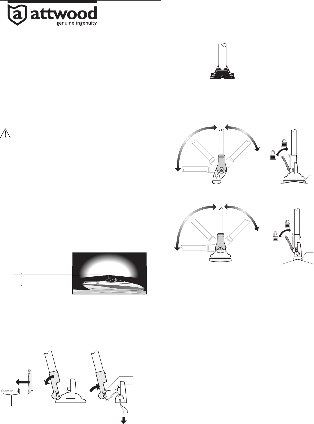
Bases are available for mounting on vertical or horizontal surfaces. Release the cam-lock
adjustment handle to fold light or adjust to vertical position.
Change Base Type (If Required) on Fold-Down Base
Packaged versions of the light are shipped with the horizontal base installed. To switch
to the vertical base:
1. Carefully remove the cam-lock screw and oblong washer. Set aside for reinstallation
(Figure 2).
2. Pivot the base axle out of its socket. Note position of the 2 wires in the base slot.
Remove the horizontal base.
3. Insert wires through slot of the vertical base. Reassemble in reverse order.
Mark Position for Fixed Base Light, (Figure 3)
1. Place light in selected position.
2. Using the base as a template, mark the two mounting hole locations and one wire
access hole. Proceed to “Install Light” below.
Mark Position for Fold-Down Light
1. Release cam-lock adjustment handle and adjust light to vertical position. (Figure 4)
2. Place light in selected position.
3. Use optional adaptors, if necessary, to allow installation on angled windshields.
4. Using the base as a template, mark the two mounting hole locations and one wire
access hole. (Figure 5) Proceed to “Install Light” below.
Figure 1
Figura 1
Figure 4
Figura 4
Figure 5
Figura 5
Figure 3
Figura 3
Install Light
CAUTION: Position wire access hole carefully, especially on aluminum boats, so that
wires do not contact the hull.
1. Remove light from marked position. Drill two 1/8" (3mm) pilot holes for #10 screws.
Drill one 3/8" (10mm) wire access hole.
2. Bring the two 16-gauge wires up through access hole.
3. Use marine-grade waterproof crimp connectors to connect gray wire to positive
lead from 3-position switch. Connect (-) negative source to black wire and route
to (-) negative terminal on battery.
4. Fasten light to deck with two #10 stainless steel pan head screws. DO NOT OVERTIGHTEN.
Base Wiring
IMPORTANT: LED-based lights MUST be wired for correct polarity.
NOTE: Do not use light pole as a fl agpole or handle.
OPERATION
After installation, check lights to verify proper operation. Regulations require lights to
be operated with a three-position switch for:
1. Running lights (sidelights and all-round light);
2. Anchor lights (all-round light only);
3. Off.
ATTWOOD LIMITED 10-YEAR WARRANTY
Because of the longevity of Attwood’s LED lighting technology, Attwood offers a limited
10-year warranty on this LED lighting product. See Product Catalog or attwoodmarine.com
for details.
Cam-lock Screw
and Oblong Washer
Vis de serrage et
rondelle oblongue
Tornillo con leva de
fijación y arandela alargada
Horizontal Base
Base horizontale
Base horizontal
Vertical Base
Base verticale
Base vertical
Feed Wires Thru
Insérez les fils à travers
Pasar los cables
Axle
Axe
Eje
Socket
Douille
Portalámparas
STEP 1
ÉTAPE 1
PASO 1
STEP 2
ÉTAPE 2
PASO 2
STEP 3
ÉTAPE 3
PASO 3
Figure 2
Figura 2