


2-Mile Transom Lights
Models 6356D and 66382
Installation Instructions
Attwood marine hardware, navigational lighting, bilge pumps, and
other marine accessories are specified more than any other brand
by America’s best-known boat manufacturers as original equipment.
Look to Attwood for quality replacement parts and marine accessories.
SAVE THESE INSTRUCTIONS
Form Number 69396 Rev. B 03-10
3
®
WARNING
Read all instructions carefully before installing and using this product.
To prevent personal injury, disconnect the power source when installing
or servicing this product. Always remove the boat from the water before
using 120V AC power tools.
Use only the fuse amperage rating specified in these instructions.
FEATURES
These Attwood Transom Lights are for use on boats up to 65.6 ft.
(20 meters). The 6356D Transom Light (Round) has a clear backing
so it shines on both sides of a bulkhead - can be used to light an
interior compartment.
6356D Transom Light meets USCG CFR 183.810, ABYC A-16
requirements, and all applicable standards as tested by Imanna
Labs, 12/20/2002. 2 Nautical-Mile visibility. Lights use 7.5-watt
lamp, #9232 (13-volt).
REQUIRED FOR INSTALLATION
• Phillips screwdriver
• Cordless drill; 1/8" (3mm) bit and 1-7/8" (48mm) hole saw
• 16-gauge wire and waterproof crimp connectors
• Fuse holder (Attwood #14341) and 1-amp fuse
INSTALLATION LOCATION
Transom Lights must be mounted:
• On the transom, exterior cabin bulkhead or superstructure. (Figure 1)
• As far aft as possible.
• On a vertical surface where the light will be unobstructed.
• So that light shines directly astern and horizontally when the boat
is floating.
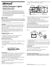
INSTALLATION
1. To access light base mounting holes, remove the 2 mounting screws,
bezel, and lens. Set these aside for reinstallation. (Figure 2)
2. Place flat side of base against a smooth vertical surface
(see INSTALLATION LOCATION for proper position).
Important: Before drilling, be sure that light will shine straight astern
and within 5° of horizontal when boat is floating.
3. Use base as a template to mark location of two mounting holes
and a center hole for wire access.
CAUTION
Position wire access hole carefully, especially on aluminum boats,
so that wires do not contact the hull.
4. Drill 1-7/8" (48mm) diameter hole for base clearance and 1/8" (3mm)
diameter holes for mounting screws. (Figure 2)
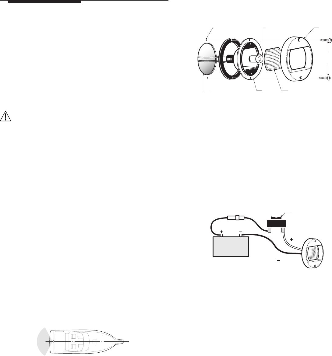
5. Bring one 16-gauge (+) and one (-) wire up through access hole.
DO NOT connect these wires to power until you read FINAL
WIRING INSTRUCTIONS. (Figure 3)
6. Connect wires using waterproof crimp connectors.
7. Place gasket and base over clearance hole. Replace lens and
bezel. Fasten assembly with two supplied mounting screws.
DO NOT OVERTIGHTEN.
FINAL WIRING INSTRUCTIONS
Connect to 12-Volt DC power source ONLY. All positive wires must
be protected by a 1-amp fuse. Higher voltage or failure to make
proper wire and fuse connections will void the product warranty.
Use crimp type marine-grade connectors with suitable insulation.
Figure 1
Figure 2
Mounting
Screws
Bezel
Base
Lens
#6356-03 (round)
#911259 (square)
Lamp
Attwood #9232
1/8" (3cm)
Pilot Hole
1-7/8" (48mm)
Base Clearance Hole
(neg)
(neg)
(pos)
(pos)
12V DC
1-Amp Fuse
3-Way Switch
Figure 3
1. Neatly thread wires to the switch, avoiding areas where abrasion
or snagging may occur.
2. Use switch (Attwood #14386 or equivalent) that allows two-position
ON/OFF/ON operation - one for running lights, and one for anchor
lights. Attach wires with crimp-on butt joint connectors. Test lights
for proper operation.
MAINTENANCE
To replace lamp or lens: Remove the bezel and lens (Figure 2).
Lamp: 7.5 watt, 12-volt (Attwood #9232).
Lens: Attwood # 6356-03 (Round) or #911259 (Square).
Replace lens, helmet, and retaining screws.
ATTWOOD LIMITED WARRANTY
This product carries the standard Attwood one-year warranty.
See Product Catalog or www.attwoodmarine.com for details.
© 2003 Attwood Corporation
1016 N. Monroe Street, Lowell, MI 49331-0260 www.attwoodmarine.com