


FEATURES
Attwood 3-mile (4.8 km) Anchor/Masthead Lights consist of anodized aluminum poles with lightweight
heads. Horizontal base allows light pole to be adjusted and locked within a 180° arc.
Lights provide a 3-mile, 225° forward running light and 2-mile all-round anchor light. For power-driven
boats boats up to 65.6 feet (20 meters). Lights meet USCG CFR 183.810, ABYC A-16 requirements,
and all applicable standards as tested by Imanna Laboratory, Inc., December 3, 2007.
CAUTION
To prevent personal injury, disconnect the power source when installing or servicing any electrical
product. Remove vessel from water when using any 120 VAC power tools.
REQUIRED FOR INSTALLATION
• Cordless drill; 1/8" and 3/8" (3 and 10mm) bits
• Marine-grade non-silicone sealant
• Phillips screwdriver
• Two #10 stainless steel counter sunk screws
• 3-position switch (OFF/ON/ON)
• Fuse holder and fuse: 1-amp (for 12-volt systems)
• 16-gauge wire
• Marine-grade wire connectors for 16-gauge wire
MOUNTING LOCATION
CAUTION
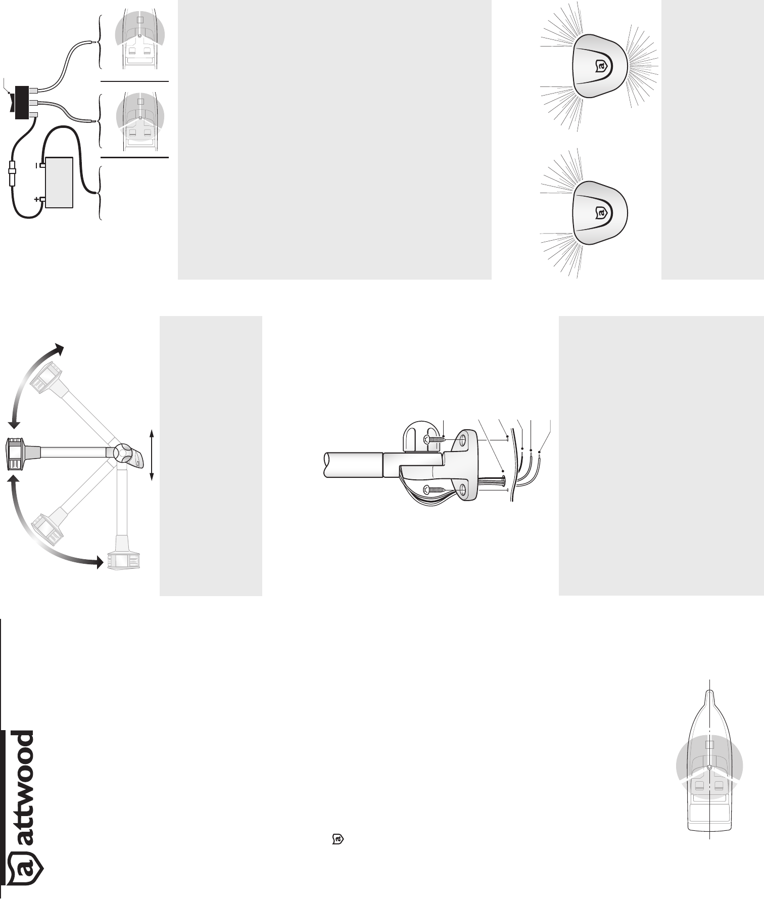
Install light so that logo stamped in the metal plate is TOWARD BOW and aligned on the
fore/aft centerline of the vessel (within 1°). If not properly aligned, lights will not shine in required
fore/aft arc. (Figure 2)
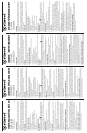
Base must pivot on the fore/aft centerline and be mounted on a surface that allows a 360° arc of
unobstructed light visibility. (Figure 1)
INSTALL LIGHT
1. Loosen knob and adjust light to vertical position. (Figure 2)
2. Place light in selected position.
3. Use adaptors, if necessary, to allow installation on angled windshields.
4. Using the base as a template, mark the two mounting hole locations and one wire access hole. (Figure 3)
CAUTION
Position wire access hole carefully, especially on aluminum boats, so that wires do not contact the hull.
5. Remove light. Drill two 1/8" (3mm) pilot holes for #10 screws. Drill one 3/8" (10mm) wire access hole.
6. Bring two 16-gauge (+) wires and one 16-gauge (-) wire up through access hole. DO NOT connect
power to switch until you read CONNECT POWER TO SWITCH.
7. Use marine-grade waterproof crimp connectors to connect blue wire to one (+) positive lead from
3-position switch; connect gray wire to second (+) lead. Connect (-) negative source to black wire
and route to (-) negative terminal on battery.
8. Fasten light to deck with two #10 stainless steel counter sunk screws. DO NOT OVERTIGHTEN.
CONNECT POWER TO SWITCH
Use ONLY the rated voltage. Higher voltage can damage light and void product warranty. All positive
(+) wires must be protected by fuse (1-amp for 12-volt).
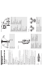
1. Use 3-position, double-pole OFF/ON/ON switch. (Figure 4)
2. Masthead (running) Lights: Gray (power +) wire should be connected to the switch so it can be
powered independent from the anchor light. This switch position can also be wired to control
other running lights i.e. bow, stern lights. (Figure 5)
3. Anchoring (All-Round) Lights: Blue (power +) wire should be connected to the switch so both
Masthead (running) lights and anchor light are powered at the same time. (Figure 5)
4. Test forward running and anchor lights for proper operation.
LED ANCHOR/MASTHEAD LIGHT
12-VOLT: 7800 Series
© 2008 Attwood Corporation
1016 N. Monroe Street, Lowell, MI 49331-0260 www.attwoodmarine.com
SAVE THESE INSTRUCTIONS
Form Number 69438 Rev. A 08-04
Figure 1
Figura 1
Abbildung 1
Figur 1
ATTWOOD LIMITED 10-YEAR WARRANTY
Because of the longevity of Attwood’s LED lighting technology, Attwood offers a limited 10-year
warranty on this LED lighting product. See Product Catalog or attwoodmarine.com for details.
AB
Figure 2
A. Forward
B. Aft
Figura 2
A. Delantero
B. Popa
Figur 2
A. framåt
B. bakåt
Figure 2
A. Avant
B. Arrière
Abbildung 2
A. Vorne
B. Achtern
Figure 2 / Figura 2
Abbildung 2 / Figur 2
B
C
D
E
F
A
Figure 3
A. #10 Counter Sunk Screw
B. 3/8" (10mm) Wire Access Hole
C. 1/8" (3mm) Pilot Hole
D. Black Wire to Ground
E. Grey Wire Mast Light (Forward)
F. Blue Wire Anchor Light (Aft)
Figure 3
A. Vis à tête fraisée plate n° 10 en acier inoxydable
B. Trou d’accès des fi ls de 10 mm
C. Avant-trou de 3 mm
D. Fil noir à la masse
E. Fil gris feu de mât (avant)
F. Fil bleu feu de mouillage (arrière)
Figura 3
A. Tornillo de cabeza fresada No. 10
B. Orifi cio para el acceso del cable de 3/8" (10 mm)
C. Agujero guía de 1/8" (3 mm)
D. Cable negro a tierra
E. Cable gris Luz de mástil (delantero)
F. Cable azul Luz de ancla (popa)
Abbildung 3
A. Senkkopfschraube Nr. 10
B. 10 mm Loch zur Durchführung der Drähte
C. 3 mm Führungsloch
D. Schwarzer Draht zum Masseanschluss
E. Grauer Draht Mastspitzenleuchte (vorwärts)
F. Blauer Draht Ankerlicht (achtern)
Figur 3
A. skruv (nr 10) med försänkt huvud
B. 10 mm kabelhål
C. 3 mm styrhål
D. svart kabel till jord
E. grå kabel mastljus (framåt)
F. blå kabel ankarlanterna (bakåt)
Figure 3 / Figura 3
Abbildung 3 / Figur 3
DC
E
JI
F
A
B
GH
Figure 4
A. 2-Amp Fuse
B. 3-Position Switch (OFF/ON/ON)
C. Positive
D. Negative
E. 12V DC
F. Black (To Negative)
G. Blue (Positive-1)
H. Gray (Positive-2)
I. Anchor Lights (All Around)
J. Masthead Lights (Running)
Figure 4
A. Fusible de deux ampères
B. Interrupteur à trois positions (arrêt/marche/marche)
C. positif
D. négatif
E. 12 volts CC
F. Noir (vers négatif)
G. Bleu (pos. - 1)
H. Gris (pos. - 2)
I. Feux de mouillage (visibles sur tout l’horizon)
J. Feux de tête de mât (navigation)
Figura 4
A. Fusible de 2 amperios
B. Interruptor de 3 posiciones
(APAGADO/ENCENDIDO/ENCENDIDO)
C. positivo
D. negativo
E. 12V DC
F. Negro (a negativo)
G. Azul (positivo 1)
H. Gris (positivo 2)
I. Luces del ancla (giratorias)
J. Luces de tope de palo (en funcionamiento)
Abbildung 4
A. Sicherung 2 A
B. Schalter mit drei Positionen
(AUS / EIN / EIN)
C. positiv
D. negativ
E. 12 V DC
F. Schwarz (an negativ)
G. Blau (Position 1)
H. Grau (Position 2)
I. Ankerlichter (rundum)
J. Fahrlicht für die Mastspitze
Figur 4
A. 2 A säkring
B. 3-vägs strömbrytare (AV/PÅ/PÅ)
C. positiv
D. negativ
E. 12V DC
F. svart (till negativ)
G. blå (pos. -1)
H. grå (pos. -2)
I. ankarlanternor (rundstrålande)
J. masttoppslampor (gångljus)
Figure 4 / Figura 4
Abbildung 4 / Figur 4
AB
Figure 5
A. Masthead Lights (Running)
B. Anchor Lights (All Around)
Figura 5
A. Luces del ancla (giratorias)
B. Luces de tope de palo (en funcionamiento)
Figur 5
A. ankarlanternor (rundstrålande)
B. masttoppslampor (gångljus)
Figure 5
A. Feux de mouillage (visibles sur tout l’horizon)
B. Feux de tête de mât (navigation)
Abbildung 5
A. Ankerlichter (rundum)
B. Fahrlicht für die Mastspitze
Figure 5 / Figura 5
Abbildung 5 / Figur 5