


.72"
1,828 cm
0,72" (18,2 mm)
.72"
1,828 cm
0,72" (18,2 mm)
1.97"
5,003 cm
1,97" (50.0 mm)
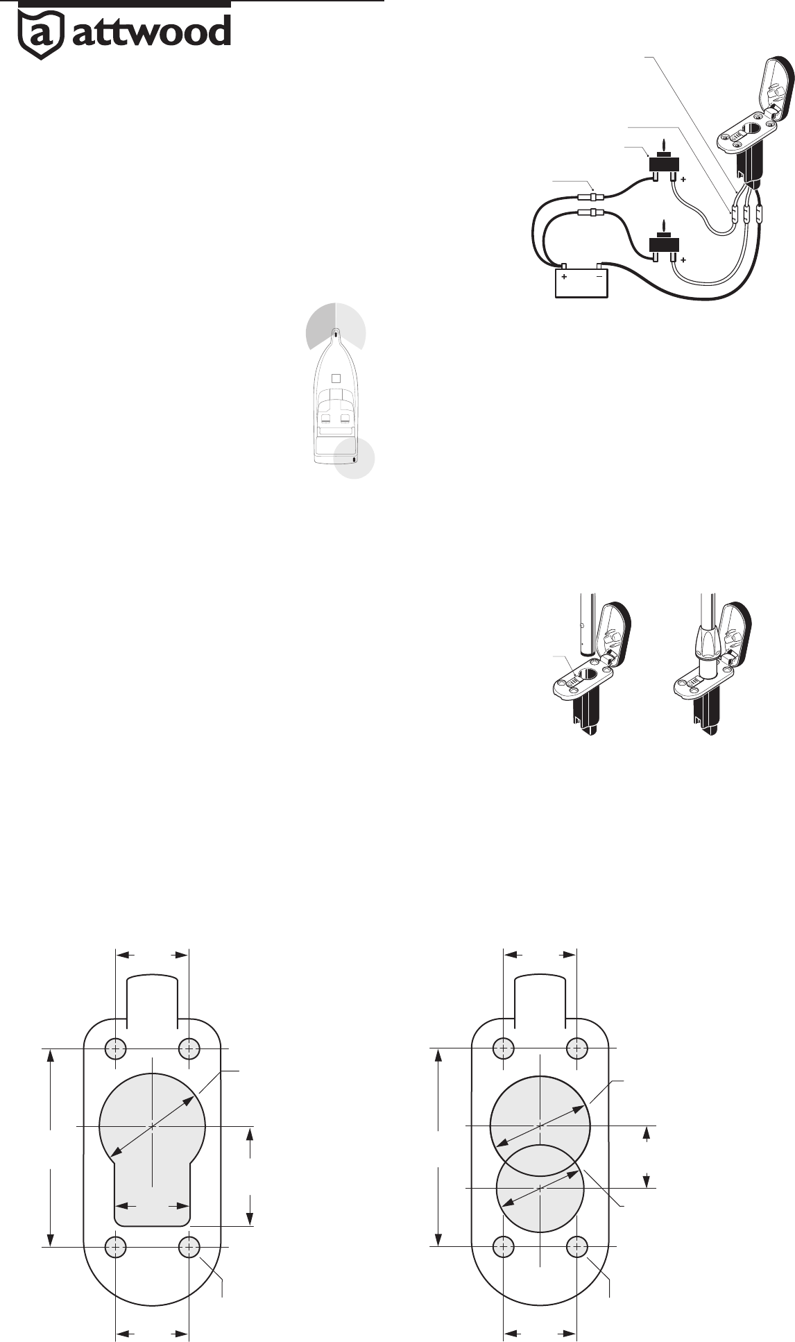
1.06" Dia. Hole
Trou de 2,69 cm de diamètre
Agujero de 1,06" (26,9 mm) de diámetro
(4) Pilot Hole Locations
Emplacements des trous de guidage (4)
(4) Ubicaciones para los agujeros guía
.76"
1.93 cm
0,76" (19,3 mm)
1"
2,54 cm
1" (25,4 mm)
.72"
1,828 cm
0,72” (18,2 mm)
.72"
1,828 cm
0,72" (18,2 mm)
1.97"
5,003 cm
1,97" (50.0 mm)
1" Dia. Hole
Trou de 2,54 cm de diamètre
Agujero de 1" (25,4 mm) de diámetro
.875 Dia. Hole
Trou de 2,22 cm de diamètre
Agujero de 0,875" (22,2 mm) de diámetro
.625"
1,58 cm
0,625" (15,8 mm)
•
•
(4) Pilot Hole Locations
Emplacements des trous de guidage (4)
(4) Ubicaciones para los agujeros guía
•
•
•
Easy Lock Light Base
91041-91044 (2-Wire), 91045-91048 (3-Wire)
SAVE THESE INSTRUCTIONS
Form Number 69423 Rev. A 08-05
© 2008 Attwood Corporation
1016 N. Monroe Street, Lowell, MI 49331-0260 www.attwoodmarine.com
FEATURES
This base is designed for use with Attwood All-Round Lights and Attwood Pole-Mounted Combination
Sidelights. The base includes a locking spring that holds the pole tightly in place.
CAUTION:
For 12-volt D.C. only.
Always disconnect the power source when installing or servicing this product. Always remove
the boat from the water before using 120V AC power tools.
REQUIRED FOR INSTALLATION
• Cordless drill
• 1/16" bit, 1" and 7/8" hole saws or bits
• 4 #10 stainless steel pan head screws suitable
for the deck material (do not use fl at head screws)
• Waterproof crimp connectors for 16-gauge wire
• Fuse-holder and fuse (amperage depends on light used)
• 2- or 3- Position switch (depending on lights used)
LOCATION
Figure 1 is a simplifi ed drawing showing placement of navigation
lights in relationship to one another.
1. For Pole-Mounted Combination Sidelights: Position the light
base at the bow and on the centerline of the boat.
2. For All-Round Lights: Position light base at the stern, on the
starboard side.
INSTALLATION
1. At the selected location, mark position for a pilot hole at exact center of the light base. (See Figure 2)
2. Before drilling, MAKE SURE that:
• Mounting surface is fl at
• You will not drill into wires, hoses, or other obstructions
• Area is large enough to fi t base (1-1/2" W x 3-3/8" L, 38mm x 86mm).
3. Drill pilot holes at both center marks. Drill clearance holes as shown below. (Figure 2)
4. Remove burrs from around the hole. On aluminum boats, be certain wires can not contact hull.
Feed wires and base socket into hole in deck.
5. For Bow Light, align base with boat centerline and place hinge toward bow. Using base as
template, mark position of mounting screws.
NOTE: If area below the base will not be reachable after installation, attach suitable lengths of
16-gauge color-matched NON-POWERED wire that can be routed to an accessible area. Make
connections according to WIRING INSTRUCTIONS (Figure 3).
6. Remove base and drill for mounting screws.
7. Gasket provided must be used instead of caulk under base to prevent locking feature
malfunction. Reinsert base, and fasten with four #10 stainless steel screws
(not provided). DO NOT OVERTIGHTEN screws.
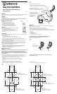
WIRING INSTRUCTIONS
CAUTION:
Failure to make proper connections and fuse the light base properly will void the product warranty.
Polarity is important. If wiring is mis-connected, LED-illuminated lights will not operate.
All positive wires must be fused according to light specifi cations to protect the circuit. MAKE
SURE POWER SOURCE IS 12-VOLT D.C. ONLY. HIGHER VOLTAGE CAN CAUSE DAMAGE TO LIGHT
AND WIRE CIRCUITRY.
1. Navigation rules require sidelights to be operated separately from anchor lights. Use either two
switches or a single switch with three positions for off / anchor / navigation (Figure 3).
2. For all wiring connections, use crimp-type marine-grade connectors with suitable waterproof
insulation. Protect all connections with suitable materials. (Figure 3)
(2 wire base):
• Connect the (-) black wire to the negative (-) wire from the 12-volt supply.
• Connect the (+) gray wire to a fused and switched positive (+) 12-volt supply.
(3 wire base):
• Connect the (-) black wire to the negative (-) wire from the 12-volt supply.
• Connect the (+) gray wire to a fused switch (+) for the navigation light.
• Connect the (+) blue wire to a fused positive (+) wire from the 12-volt supply.
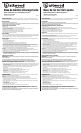
OPERATION
NOTE: This base accepts many non-Attwood light poles. However, the locking function does not
operate with other manufacturers’ poles.
NOTE: Attwood Locking Collar stays above the Easy Lock Base
1. Align pole screw with locking spring. Insert pole into base (Figure 4).
2. Press down fi rmly to engage electrical connectors. Be sure locking spring clicks over pole screw.
3. On poles with Attwood Locking Collar do not try to insert collar into base; allow collar to remain
above base.
4. To remove pole:
• Pull locking spring back
• Pull pole straight up.
5. Close cover to protect contacts when not in use.
TO CONVERT POLE FOR USE WITHOUT LOCKING COLLAR
1. Remove screw at bottom of pole. Slide locking collar off end of pole.
2. Replace screw in the upper screw hole.
This product carries the standard Attwood one year warranty. See Product Catalog or
attwoodmarine.com for details.
Figure 1
Figura 1
Figure 3
Figura 3
Figure 2
Figura 2
(neg)
(nég)
(negativo)
(pos)
(pos)
(positivo)
12V DC
12 Volts CC
12 voltios de CC
Fuse Must Match Light Specs
Les fusibles doivent correspondre
aux spécifications de la lumière
El fusible debe respetar
las especificaciones
de iluminación
Waterproof Butt-Joint Connectors
Connecteurs par raccordement en about imperméables
Conectores con juntas impermeables en los extremos
Note: Blue Wire is for 3-Pin Installations
Remarque : le fil bleu sert aux installations à trois broches
Importante: El cable azul se utiliza en instalaciones de 3 clavijas
Switch
Interrupteur
Interruptor
Blue
Bleu
Azul
Gray
Gris
Black
Noir
Negro
Figure 4
Figura 4
Locking Spring
Ressort de verrouillage
Resorte de seguridad