


1-5
Catalyst Switch Module 3110G, 3110X, and 3012 for IBM BladeCenter Hardware Installation Guide
OL-12192-01
Chapter 1 Product Overview
Hardware Features
Switch Module LEDs
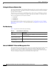
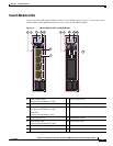
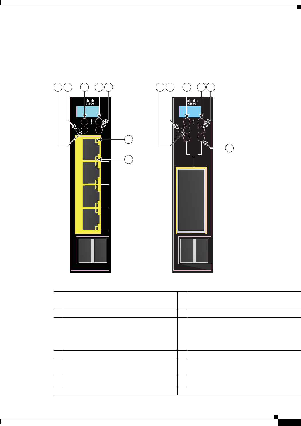
You can use the switch module LEDs to monitor switch module activity. Figure 1-3 shows the switch
module LEDs and the Mode button that you use to activate the different modes.
Figure 1-3 Switch Module LEDs and Mode Button
1 Stack member LED
(Catalyst Switch Module 3110G)
8 Stack member LED
2 Mode button 9 Mode button
3 Fault/stack mode LED
(Catalyst Switch Module 3110G)
Fault LED
(Catalyst Switch Module 3012)
10 Fault/stack mode LED
4 System power LED 11 System power LED
5 Stack master LED
(Catalyst Switch Module 3110G)
12 Stack master LED
6 Port link LED 13 X2 port status LEDs
7 Port activity LED
LNK
ACT
LNK
ACT
LNK
ACT
LNK
ACT
201896
C
O
N
S
O
L
E
M
O
D
E
C
O
N
S
O
L
E
M
O
D
E
M
B
R
M
S
T
M
S
T
15
16
17
18
STACK
21
STACK
21
M
B
R
10
6
7
11
9 12
13
8
3 4
2 5
1
X2