


B-1
Catalyst Switch Module 3110G, 3110X, and 3012 for IBM BladeCenter Hardware Installation Guide
OL-12192-01
APPENDIX
B
Connector and Cable Specifications
This appendix describes the cables and adapters that you use to connect the Catalyst Switch
Module 3110G, 3110X, and 3012 to other devices. This appendix includes these sections:
• “Connector Specifications” section on page B-1
• “Cable and Adapter Specifications” section on page B-2
Connector Specifications
These sections describe the connectors used with the switch modules:
• 10/100/1000 Ports, page B-1
• 10-Gigabit Ethernet Module Interface, page B-2
• Console Port, page B-2
10/100/1000 Ports
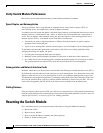
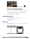
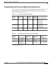
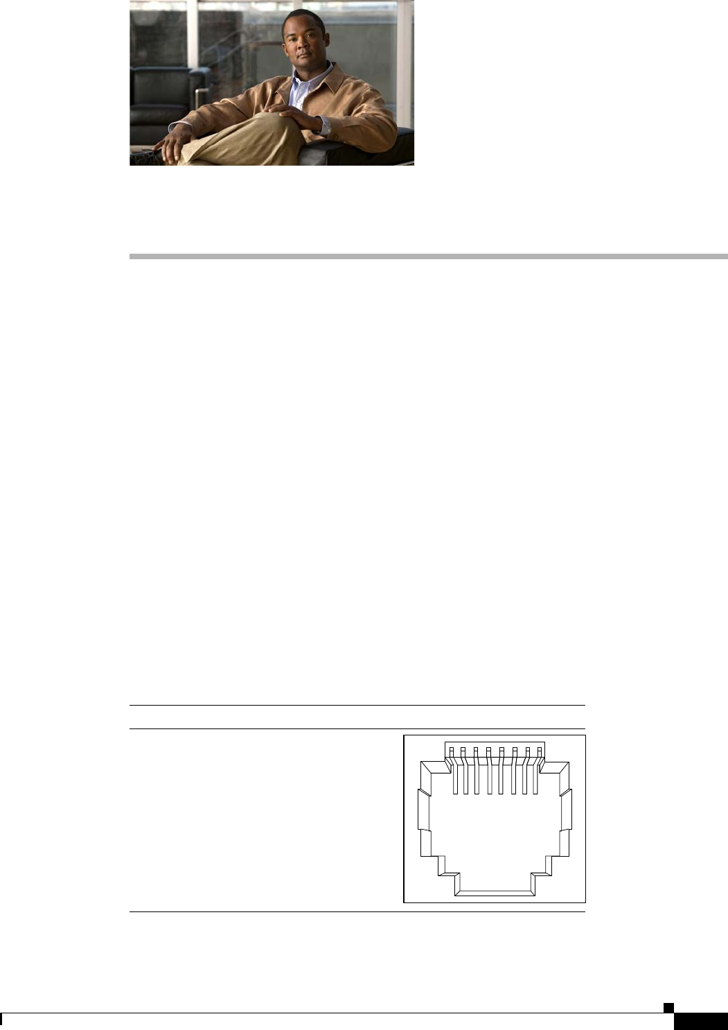
The 10/100/1000 Ethernet ports on switch modules use standard RJ-45 connectors and Ethernet pinouts.
Figure B-1 shows the pinouts.
Figure B-1 10/100/1000 Port Pinouts
60915
2 3145678Pin Label
1
2
3
4
5
6
7
8
TP0+
TP0-
TP1+
TP2+
TP2-
TP1-
TP3+
TP3-