


B-3
Catalyst Switch Module 3110G, 3110X, and 3012 for IBM BladeCenter Hardware Installation Guide
OL-12192-01
Appendix B Connector and Cable Specifications
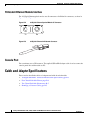
Cable and Adapter Specifications
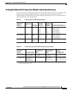
10-Gigabit Ethernet X2 Transceiver Module Cable Specifications
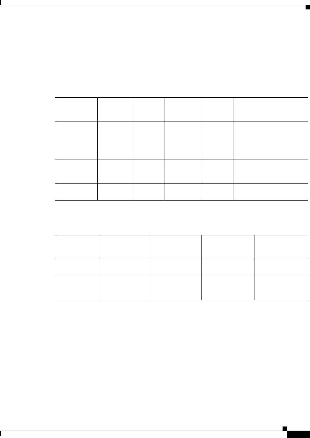
Table B-1 lists the port cabling specifications for the 10-Gigabit Ethernet X2 transceiver modules. Each
port must match the wave-length specifications on the other end of the cable, and for reliable
communications, the cable must not exceed the stipulated cable length.
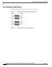
Table B-2 lists the transceiver
optical transmit and receive specifications.
Table B-1 X2 Transceiver Port Cabling Specifications
X2 Product
Number
Wavelength
(nm)
Cable Type
Core Size
(microns)
Modal
Bandwidth
(MHz/km)
Maximum Cabling Distance
X2-10GB-SR 850 MMF 62.5
62.5
50.0
50.0
50.0
160
200
400
500
2000
85 feet (26 m)
108 feet (33 m)
217 feet (66 m)
269 feet (82 m)
984 feet (300 m)
X2-10GB-LX4 1310 MMF
1
1. Mode conditioning patch cord is recommended for MMF applications.
62.5
50.0
50.0
500
400
500
984 feet (300 m)
787 feet (240 m)
984 feet (300 m)
X2-10GB-CX4 — InfiniBand
(copper)
— — 49 feet (15 m)
Table B-2 X2 Transceiver Optical Transmit and Receive Specifications
X2 Product
Number
Transceiver Type
Transmit Power
(dBm)
Receive Power
(dBm)
Transmit and
Receive
Wavelength (nm)
X2-10GB-SR 10GBASE-SR,
850-nm MMF
–1
1
(Max)
–7.3 (Min)
1. The launch power shall be the lesser of the Class 1 safety limit or the maximum receive power. Class 1 laser requirements
are defined by IEC 60825-1: 2001.
–1.0 (Max)
–9.9 (Min)
840 to 860
X2-10GB-LX4 10GBASE-LX4
WWWDM
1300-nm MMF
–0.5 per lane (Max)
—
–0.5 (Max)
–14.4 per lane
Four lanes; overall
range: 1269 to 1356