


2-7
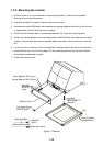
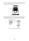
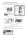
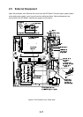
2.2.3 Leading in cables to the processor unit
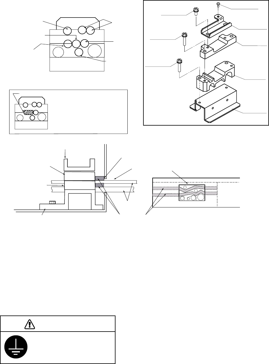
Cables are led in to the processor unit through the cable clamp at the rear of the unit. Use the
shielding foam (supplied) as below to protect against noise radiation.
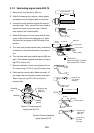
Pan-head screw
M4X8
Hex bolt
M5X12 SUS
2 pcs
Hex bolt
M5X35 SUS
2 pcs
Hex bolt
M5X35 SUS
2 pcs
(A) Rear clamp
base
(B) Power clamp
(Aluminum)
(C) Signal clamp
(Aluminum)
(D) Rear clamp
plate
Cable position in cable clamp
(Processor unit, rear view)
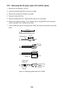
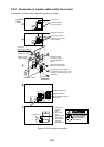
PWR
ANT
Log*
Control
unit
Nav equipment
(Gyro, etc.)
Slave display
Monitor
(Construction of
cable clamp)
(B) Power clamp
(Aluminum)
(C) Signal cable
(Aluminum)
(D) Rear clamp plate
(A) Rear clamp base
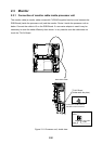
Rear cable entrance
Cable
Shielding foam
(Processor unit, right-hand side view)
(Processor unit, rear view)
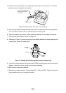
Make sure shielding foam contacts rear chassis.
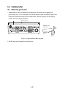
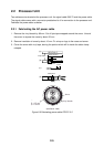
Navigator*
* When no log or nav equipment is
installed, insert rubber plug
(supplied) to the left of keyboard
cable to hold the cable in place.
Rubber plug
Figure 2-10 Cable clamp position
•
Place shielding foam between cables, and then attach foam to aluminum clamps.
•
Fill unused clamp holes with shielding foam.
•
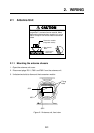
Connect a ground wire between the earth terminal on the processor unit and ship's
superstructure.
Ground the equipment to
prevent electrical shock
and mutual interference.
CAUTION