


33
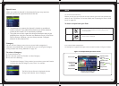
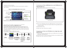
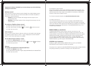
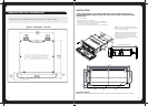
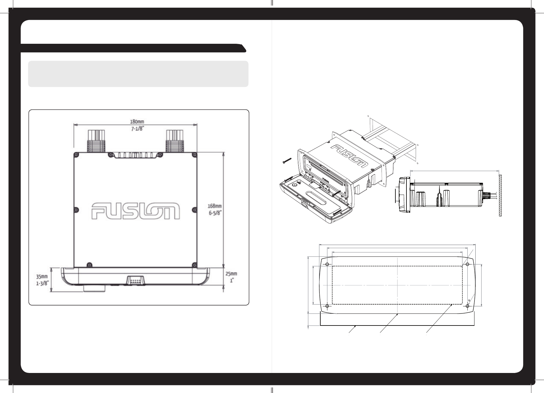
INSTALLING THE 700 SERIES
Dimensions are in millimeters (mm) and inches (”). Not to scale.
Figure 7 – Dimensions - top view
38
53.0 (2-3/32”)
181.0 (7-1/8”)
R
2.0 (3/32”)
58.0 (2-9/32”)
195.0 (7-11/16”)
4.0 (5/32”)
79.0 (3-1/8”)
217.0 (8-9/16”)
16.5 (5/8”)
PRODUCT OUTLINE
CUTOUT
DOOR OPENING CLEARANCE
Recommended Clearance 205 (8-3/32”)
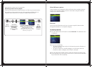
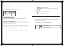
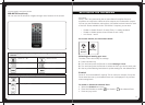
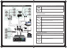
ELECTRICAL WIRING
Caution: The MS-IP700 and MS-AV700 are designed for vessels with a 12V DC Negative ground electrical system.
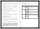
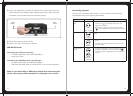
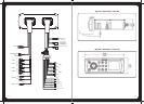
INSTALLATION
IF ANY MODIFICATION TO THE VESSEL IS REQUIRED, SUCH AS DRILLING HOLES ETC,
FUSION RECOMMENDS CONSULTATION WITH YOUR BOAT DEALER OR MANUFACTURER
BEFOREHAND.
>> Fit mounting gasket
>> Insert the unit into the mounting hole
>> Pull down the front face to expose the mounting screw locations
>> Use either the supplied 4 x wood screws, or 4 x machined screws
and metal clamps to affix the unit into position.
>> The unit must be mounted within 30 degrees of the horizontal plane.
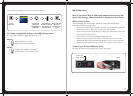
Note: In some circumstances a back strap or
brace may be required at the rear of the unit (Back
Strap / Brace is not included).
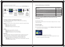
Appropriate mounting is very important to ensure
correct operation. Select a location that allows
both free/open airflow around the rear of the
chassis, whilst minimizing exposure to moisture.
Allow adequate room at the rear of the unit for the
cable looms (approx 2 - 3”).