


35
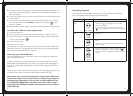
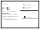
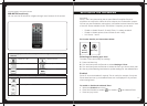
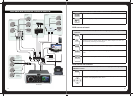
DESCRIPTION COLOUR
Battery +12VDC Yellow
Accessory +12V switched Red
Negative Ground Black
Remote Amplifi er Enable ouput Blue/White
Dim input [12VDC active] Orange
Telemute input [GND active] Brown
Note: All +12V wiring MUST be fused at the power source end of your cable, with
a 15 A fuse. When the red “Accessory +12V switched” wire is not required in your
installation, it MUST be connected together with the Yellow “Battery +12V” wire at the
MS-700 head unit wiring loom.
When connecting the Dim input ensure the wire gauge used is suitable for the fuse
supplying the circuit being connected to.
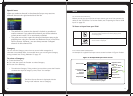
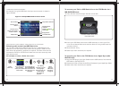
ANTENNA CONNECTION
Connect an AM/FM marine antenna.
Note: Do Not Connect to a VHF splitter
AUX INPUT
Connect an Auxiliary source to the left and right RCA (White = L, Red = R).
VIDEO CONNECTION
(MS-IP700 iPod/iPhone video only, MS-AV700 DVD video only)
Connect the composite video output (Yellow = Video) to a TV / LCD monitor
USB CONNECTION (MS-AV700 only)
Connect an Apple sync cable (not included), or USB Flash Drive (not included) or
connect the MS-DKIPUSB Portable Media Device Dock (not included)
Note: MS-IP700 has internal USB socket
NMEA2000 / WIRED REMOTE
For connection to a MS-NRX200 Remote (not included).
For connection to an existing NMEA2000 Bus a MS-N2KCONN is required (not
included)
To install a new NMEA2000 Bus a MS-N2KSTART is required (not included)
CONNECTIONS
36
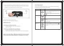
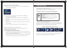
ETHERNET CONNECTION
For connection to a DHCP Ethernet Router for communication with FUSION-Link
capable devices.
SIRIUS XM SATELLITE RADIO (For use in USA only)
Connect to Sirius XM tuner module SVX100 (not included)
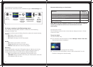
ZONE CONNECTIONS
Zone 1 White = Speaker Left Positive
White / Black = Speaker Left Negative
Grey = Speaker Right Positive
Grey / Black = Speaker Right Negative
Zone 2 Green = Speaker Left Positive
Green / Black = Speaker Left Negative
Purple = Speaker Right Positive
Purple / Black = Speaker Right Negative
Note: Speaker connection (2 Ohm Stereo minimum). 2 pairs of 4 Ohm speakers per
channel can be connected in parallel to achieve 2 Ohm confi guration
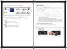
Zone 1 Line Out (Red wire) Low level output
(For connection to external amplifi er)
White RCA = Left Output
Red RCA = Right Output
Brown RCA = Subwoofer Output
Zone 2 Line Out (White wire) Low level output
(For connection to external amplifi er)
White RCA = Left Output
Red RCA = Right Output
Brown RCA = Subwoofer Output
Zone 3 Line Out (Grey wire) Low level output
(For connection to external amplifi er)
White RCA = Left Output
Red RCA = Right Output
Brown RCA = Subwoofer Output
Zone 4 Line Out (Black wire) Low level output
(For connection to external amplifi er)
White RCA = Left Output
Red RCA = Right Output
Brown RCA = Subwoofer Output