


28 GHP 10 Marine Autopilot System Installation Instructions
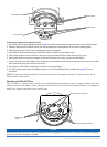
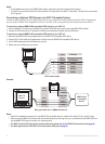
Wiring the Alarm Buzzer
Wire the alarm buzzer to the CCU/ECU interconnect cable.
To wire the alarm buzzer:
1. Route the alarm-buzzer cable to the bare-wire end of the CCU/ECU interconnect cable. If the cable is not long enough, extend the
appropriate wires with 28 AWG wire.
2. Use the Alarm Buzzer Wiring Table to make the appropriate connections.
Alarm Buzzer Wire Color CCU/ECU Interconnect Cable Wire Color
White (+) Red (+)
Black (-) Blue (-)
Alarm Buzzer Wiring Table
3. Solder and cover all bare-wire connections.
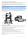
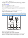
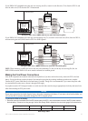
Installing the GHC 10
Install the GHC 10 by ush-mounting it in the dashboard near the helm, connecting it to the yellow CCU signal wire from the CCU/
ECU interconnect cable, and connecting it to a NMEA 2000 network. Optionally, you can connect the GHC 10 to a NMEA 2000 or
NMEA 0183-compatible GPS device to use waypoint and route data.
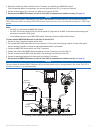
Mounting the GHC 10
Flush mount the GHC 10 in the dashboard near the helm.
When you select an installation location for the GHC 10, choose a location with the following characteristics:
Provides optimal viewing as you operate your vessel.
Allows easy access to the keypad on the GHC 10.
Is strong enough to support the weight of the GHC 10 and protect it from excessive vibration or shock.
Allows room for the routing and connection of the cables. There should be at least a 3-inch (8 cm) clearance behind the case.
Is at least 9
1
/
2
in. (0.24 m) from a magnetic compass, to avoid interference.
Is in an area that is not exposed to extreme temperature conditions.
NOTICE
The temperature range for the GHC 10 is from 5°F to 158°F (from -15°C to 70°C). Extended exposure to temperatures outside of this
range (in storage or operating conditions) may cause failure of the LCD screen or other components. This type of failure and related
consequences are not covered by the manufacturer’s limited warranty.
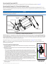
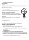
To ush mount the GHC 10:
1. The ush-mount template is included in the product box. Trim the template and ensure it will t in the location at which you want to
ush mount the GHC 10.
2. The ush-mount template has adhesive on the back. Remove the protective liner and
apply the template to the location where you want to ush mount the GHC 10.
3. If you will be cutting the hole with a jigsaw, and not a 3
17
/
32
in. (90 mm) hole saw, use a
3
/
8
in. (10 mm) drill bit to drill a pilot hole as indicated on the template to begin cutting the
mounting surface.
4. Using the jigsaw or the 3
17
/
32
in. (90 mm) hole saw, cut the mounting surface along
the inside of the dashed line indicated on the ush-mount template. Use a le and
sandpaper to rene the size of the hole.
5. Place the GHC 10 into the cutout to conrm that the four mounting holes are correct
after rening the hole. If not, mark the correct locations of the four mounting holes.
Remove the GHC 10 from the cutout.
6. Using the center punch, indent the center of each of the four pilot-hole locations.
•
•
•
•
•
•