


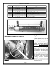
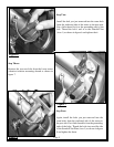
Put a little thread lock on the ends of the three 6
MM Hex CAP Screws (item 6) and install them
through one Lock Washer each (item 11) and then
the Cylinder Mounting Channel (item 4) and into
the Standoff Nut and Plate (items 1 & 5) as shown
in gure 9. (Channel with the label facing you right
side up.) Keep the Channel perpendicular to the
motor down shaft and tighten the Screws.
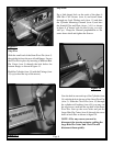
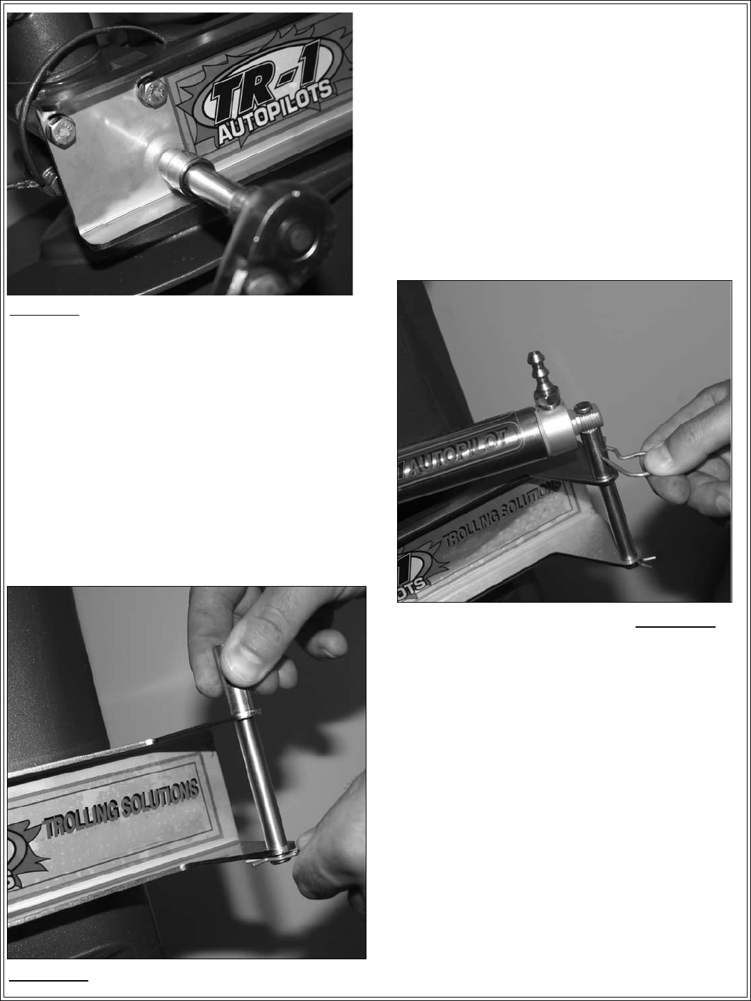
Slide the small end of the Stern Pivot Pin (item 3)
through the holes at the rear of both anges. Secure
the Pivot Pin in place by inserting a Medium Hair
Pin Cotter (item 9) through the hole below the
bottom ange, as shown in gure 11.
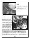
Hold the Cylinder (item 34) with the Fittings (item
35) up (toward the top of the motor).
Line the hole in rear end cap of the Cylinder (item
34) with the hole in the top of the Stern Pivot Pin
(item 3). Slide the Clevis Pin (item 10) through
the cylinder tail bushing (item 40) (you may cut
the zip tie now) and into the top hole of the Stern
Pivot Pin. Line up the cross holes and put the
Large Hair Pin Cotter (item 8) through the cross
holes in both Pins as shown in gure 10.
NOTE: If for any reason you need to
disconnect the steering actuator, pulling the
large Hair Pin Cotter and Clevis Pin will
disconnect them quickly.
Page 6
Figure 9
Figure 10
Figure 11
Step Four:
Step Five: