


3–10 EPM 5300 SERIES ADVANCED POWER METERS – INSTRUCTION MANUAL
ELECTRICAL CONNECTION INSTALLATION CHAPTER 3: ELECTRICAL INSTALLATION
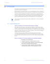
3.6 Electrical Connection Installation
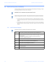
Choose the diagram that best suits your application and maintain the CT polarity. Follow
the outlined procedure to verify correct connection.
Note
IMPORTANT: For PT connections only, short terminals 3 and 4.
Note
Connect local ground to terminal 3. This protects the unit from spikes and transients.
• The meter and terminal module DSP3 are factory calibrated together; the serial
numbers are matched on both. The DSP3 input module and the meter base MUST
MATCH!
• Mismatching of the meter and DSP3 input module will cause inaccurate readings
because calibration ratios are stored in the meter’s memory, not in the DSP3 input
module.
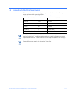
3.6.1 List of Connection Diagrams
Note
See phase reversal if a message of CBA appears after installation.
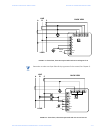
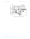
Fig 3-1 Three-Phase, Three-Wire System Delta with Direct Voltage and CTs
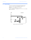
Fig 3-2
Three-Phase, Three-Wire Open Delta with two CTs and two PTs
(Open Delta System should only be used if the electrical system is a 3-wire 2
PT OPEN DELTA
Open Delta can be enabled or disabled in Programming GROUP 0,
FUNCTION 3, Chapter 9, section 9.4)
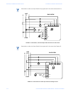
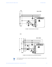
Fig 3-3 Three-Phase, Three-Wire Open Delta with three CTs and two PTs
Fig 3-4 Three-Phase, Four-Wire Wye with Direct Voltage and CTs
Fig 3-5 Three-Phase, Four-Wire Wye with CTs and PTs
VI Single Phase with CT and PT Connection
VII Dual-Phase System
VIII Three Phase System