


CHAPTER 9: PROGRAMMING GROUP 0 - GLOBAL METER SETUP GROUP 0, FUNCTION 3 — SYSTEM CONFIGURATION
EPM 5300 SERIES ADVANCED POWER METERS – INSTRUCTION MANUAL 9–57
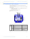
9.3 Group 0, Function 3 — System Configuration
The System Configuration sets the EPM 5300P’s basic operational parameters. This
Function utilizes Switch PACKS.
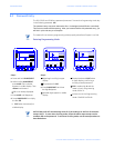
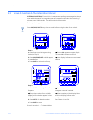
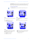
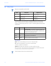
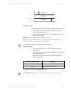
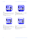
FUNCTION 3 contains four different Switch PACKS: 0–3. Each PACK contains four individual
UP/DOWN segments.
• Toggling the segment between UP and DOWN, toggles the switch ON or OFF, or
chooses between two options.
• The meter displays one Switch PACK at a time.
Press VOLTS to scroll from PACK to PACK.
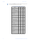
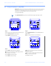
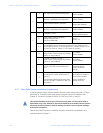
Pack Switch Feature Segment Position
0
AReserved —
bReserved —
cReserved —
d Phase Reversal Limit Detection
UP: Enable
DOWN: Disable
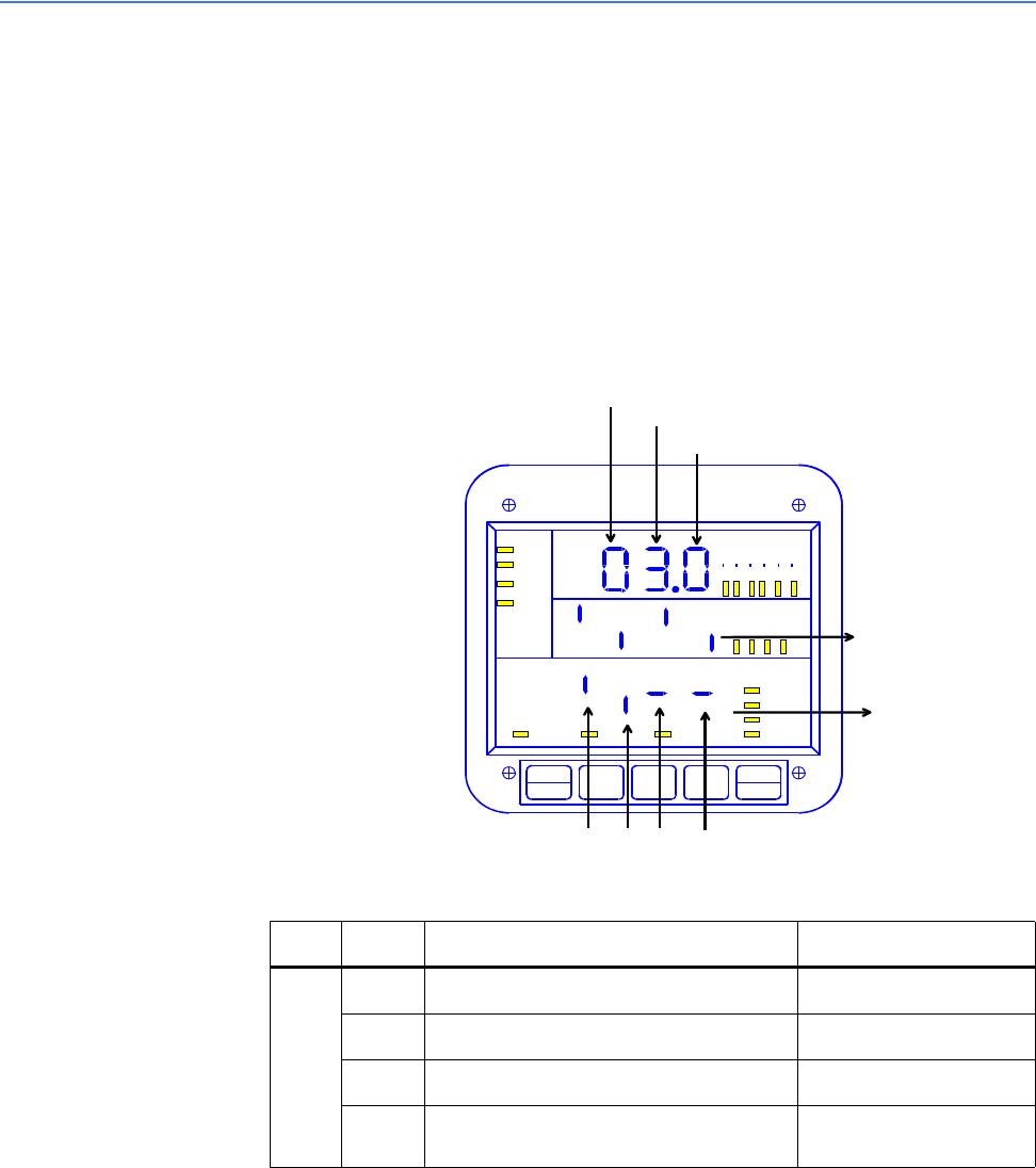
GROUP
FUNCTION
PACK
PREVIOUS
SETTING
NEW
SETTING
A
B C D
SWITCHES:
MAX/MIN
LIMIT
KVAR
PF
KW
KVA
FREQ
KWH
KVAH
A
C VOLTS
AC AMPS
POWER
NC
B
A
MAX
MIN
A
N
B
N
C
N
A
B
B
C
C
A
LM2
LM1
NEXT
PHASE
VOLT
AMP
S
POWER