9–62 EPM 5300 SERIES ADVANCED POWER METERS – INSTRUCTION MANUAL
RELAY MODE CHAPTER 9: PROGRAMMING GROUP 0 - GLOBAL METER SETUP
9.6 Relay Mode
Note
Relays are not available for the EPM 5200P.
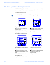
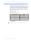
The Switch PACKS in FUNCTIONS 4 and 5 of programming GROUP 0 control the relay
position. Setting the switches in different combinations allows the user to specify the
conditions in which the relay will be “SET” or “RESET.” The following table indicates possible
configurations.
DEFINITIONS:
RESET: There is a short between “COM” and “N.C.” (Normally closed)
SET: There is a short between “COM” and “N.O.” (Normally open)
(See Part I: Installation and Operation.)
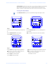
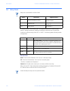
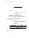
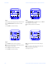
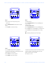
EXAMPLE 1: Fail-safe mode normally set—non-event condition is set relay
Relay 1 will be “SET” if the instantaneous reading for frequency is between 58 Hz and 62
Hz. When all other conditions exist, the relay will “RESET.”
Note
Under this setup the relay acts as a protective switch.
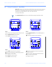
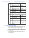
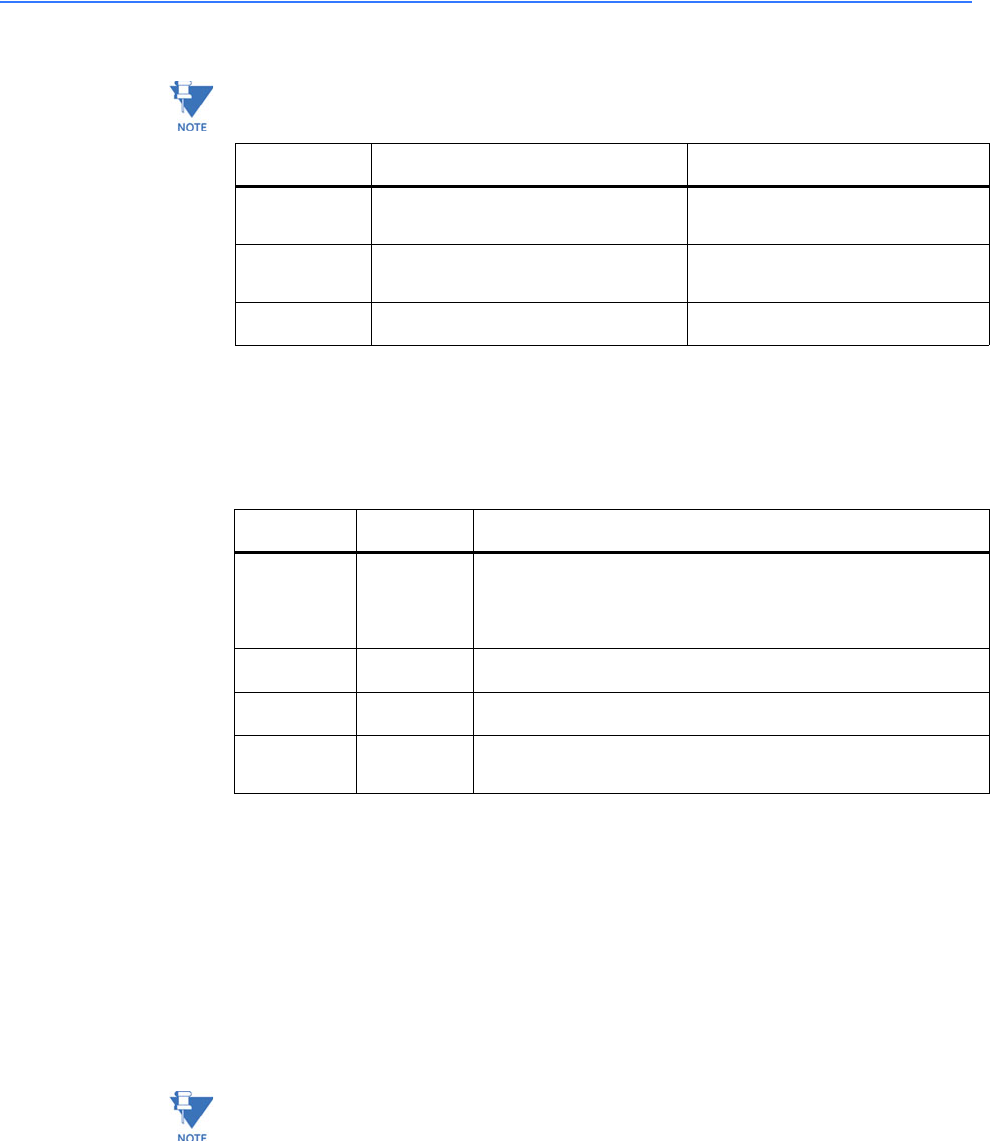
Switch Description Segment Position
A Reversal Imbalance Control
UPEnable
DOWNDisable
BAND/OR Logic
UPAND
DOWNOR
C & D Relay Control see Table 8-4
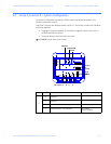
Switch C Switch D Description
UP UP
FAIL-SAFE MODE—The normal or non-event condition is set.
RESET relay on either out of limit condition. Relay acts as a
protective switch if power is interrupted. This alerts the user if
the meter or the meter power is out.
UP DOWN N/A (Reserved for future features).
DOWN UP N/A (Reserved for future features).
DOWN DOWN
RESET MODE—The normal or non-event condition is reset.
SET relay on either out of limit condition.


