


1–2 EPM 5300 SERIES ADVANCED POWER METERS – INSTRUCTION MANUAL
SINGLE PHASE SYSTEM CHAPTER 1: AC POWER MEASUREMENT
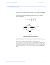
The power (W) in a single phase system is:
E = potential, I = current, and cosΘ = phase difference between the potential and the
current.
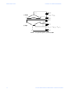
Power in a 120/240V AC system is:
Phase differential between the potential and the current results from a non-resistive load,
either reactive or capacitive.
Reactive power (VAR): The additional power consumed that does not produce any work
but must be delivered to the load: .
This is a measure of the inefficiency of the electrical system.
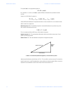
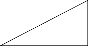
Apparent power (VA): The total power delivered to the load, and the vector sum of real
power and reactive power.
Power Factor (PF): The ratio between real power and apparent power:
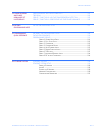
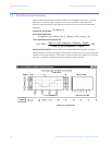
FIGURE 1–2: Relationship between apparent, real and reactive power
Ideal power distribution should have a PF of 1. This condition can be met only if no reactive
power loads exist. In real life applications, many loads are inductive loads. Often, corrective
capacitors are installed to correct Poor Power Factor (see Section 1.3).
Θcos • I • E = W
)cos • I • (E + )cos • I • (E = W
2 Line2 Line1 Line1 Line
ΘΘ
Θ⋅⋅ insIE=VAR
Apparent Power (VA)
Real Power (W)
Reactiv
e
Power
(VAR)