


6 306531Z1
Installation
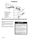
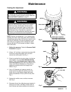
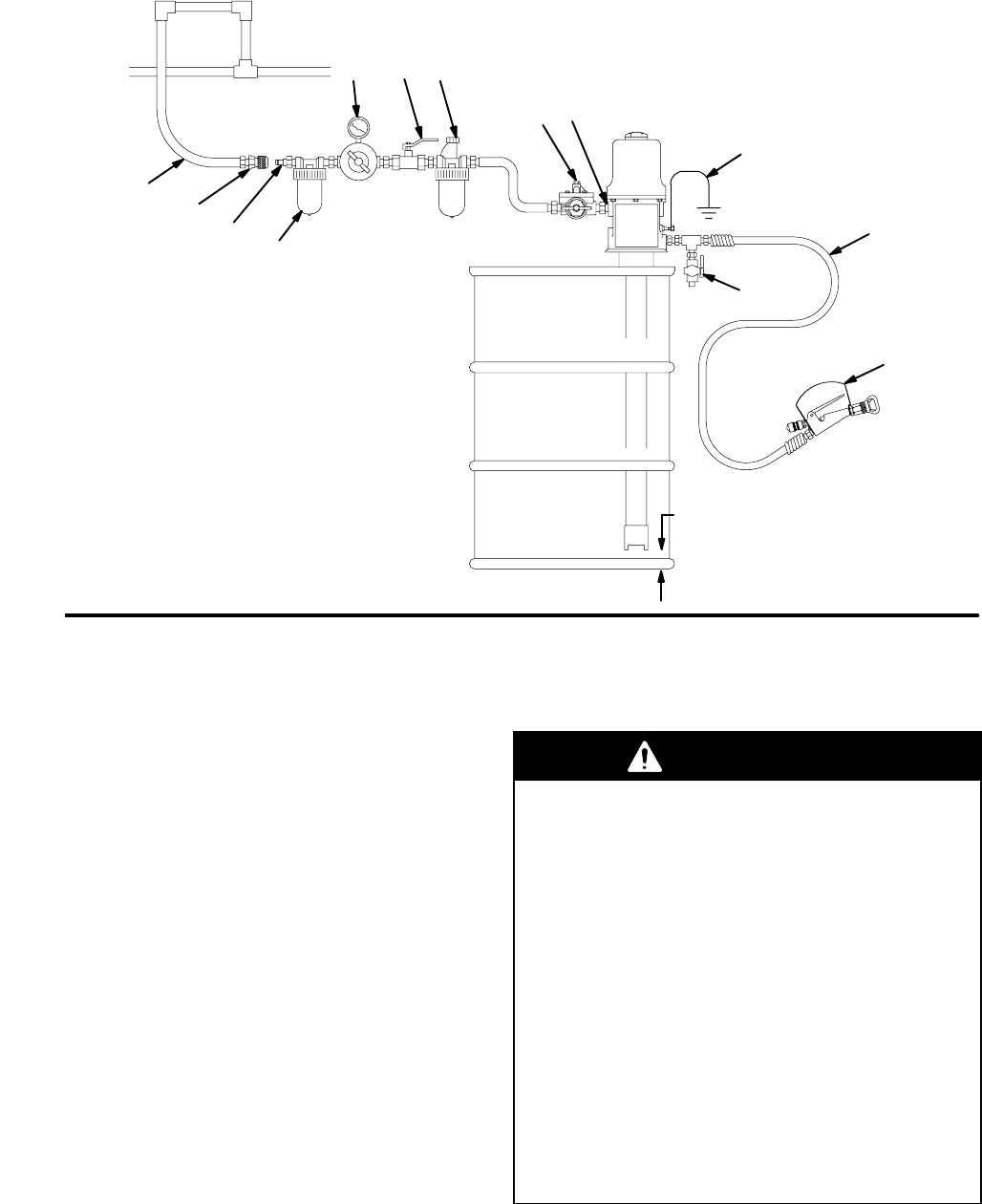
Fig. 1
KEY
A Electrically Conductive Air Hose
B Female Quick Disconnect Coupler
C Male Quick Disconnect Fitting
D Air Line Filter
E Air Regulator and Gauge
F Bleed-Type Master Air Valve
G Air Line Lubricator
H Pump Runaway Valve
J Pump Air Inlet
K Ground Wire
L Pressure Drain Valve
M Electrically Conductive Fluid Hose
N Spray Gun
A
C
E
FG
JH
M
L
B
D
N
1/2 in.
(13 mm)
K
04209
NOTE: Reference numbers and letters in parentheses
in the text refer to the callouts in the figures and the
parts drawings.
Figure 1 is only a guide to selecting and installing
optional and required accessories. For help in design-
ing a system to suit your needs, contact your Graco
distributor.
Mount the pump to suit the type of installation planned.
See page 23 for dimensions and mounting hole layout.
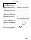
System Accessories
WARNING
To reduce the risk of serious injury including skin
injection, splashing in the eyes or on the skin, and
injury from moving parts, if you are adjusting or
repairing the pump, two accessories are required
in your system: a bleed-type master air valve (F)
and a pressure drain valve (L).
The bleed-type master air valve (F) relieves air
trapped between it and the air motor after the air
supply is shut off. Trapped air can cause the air
motor to cycle unexpectedly if you are adjusting or
repairing the pump. Install the valve near the pump
air inlet, within easy reach of the pump.
The pressure drain valve (L) assists in relieving
fluid pressure in the displacement pump, hoses
and gun. Triggering the spray gun to relieve pres-
sure may not be sufficient.