


6 307013
Installation
NOTE: Reference numbers and letters in parentheses
in the text refer to the callouts in the figures and the
parts drawing.
NOTE: Accessories are available from your Graco
distributor. If you supply your own accessories, be sure
the are adequately sized and pressure-rated to meet
the system’s requirements.
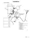
The Typical Installation shown on page 5 is only a
guide for selecting and installing system components
and accessories. Contact your Graco distributor for
assistance in designing a system to suit your particular
needs.
System Accessories
Refer to the Typical Installation on page 5.
WARNING
Two accessories are required in your system: a
bleed-type master air valve (D) and a fluid drain
valve (J). These accessories help reduce the risk
of serious injury including splashing in the eyes or
on the skin, and injury from moving parts if you are
adjusting or repairing the pump.
The bleed-type master air valve relieves air trapped
between this valve and the pump after the air is
shut off. Trapped air can cause the pump to cycle
unexpectedly. Locate the valve close to the pump.
The fluid drain valve assists in relieving fluid pres-
sure in the displacement pump, hose, and gun.
Triggering the gun to relieve pressure may not be
sufficient.
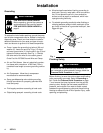
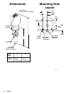
Mounting Accessories
Mount the pump (A) to suit the type of installation
planned. The pump dimensions and mounting hole
layout are shown on page 14. Use 3/8 in. bolts, lock-
washers, and nuts to attach the pump firmly to the
mounting.
Air and Fluid Hoses
Be sure all air and fluid hoses are properly sized and
pressure-rated for your system. Use only electrically
conductive air and fluid hoses. Fluid hoses must have
spring guards on both ends.
Connect a electrically conductive fluid hose (H) to the
pump’s 1” npt(f) fluid outlet, using a suitable adapter.
Connect a fluid suction hose and tube (M) to the
pump’s 1–1/2” npt(f) fluid intake.
Use an electrically conductive 3/4 in. ID (minimum) air
hose (H) to supply air to the pump.
Air Line Accessories
Install the following accessories in the order shown in
the Typical Installation, using adapters as necessary:
D An air line lubricator (C) provides automatic air
motor lubrication.
D A bleed-type master air valve (D) is required in
your system to relieve air trapped between it and
the motor when the valve is closed (see the WARN-
ING at left). Be sure the bleed valve is easily ac-
cessible from the pump, and is located downstream
from the air regulator.
D A pump runaway valve (B) senses when the
pump is running too fast and automatically shuts off
the air to the motor. A pump which runs too fast can
be seriously damaged. Install closest to the pump
air inlet.
D An air regulator (E) controls pump speed and
outlet pressure by adjusting the air pressure to the
pump. Locate the regulator close to the pump, but
upstream from the bleed-type master air valve.
D An air line filter (F) removes harmful dirt and
moisture from the compressed air supply.
D A second bleed-type air valve (G) isolates the air
line accessories for servicing. Locate upstream
from all other air line accessories.
Fluid Line Accessories
Install the following accessories in the order shown in
the Typical Installation, using adapters as necessary:
D A fluid drain valve (J) is required in your system
to relieve fluid pressure in the hose and gun (see
the WARNING at left).
D A spray gun (L) dispenses the fluid. The gun
shown in the Typical Installation is an airless spray
gun.
Air Motor Exhaust
To route the air motor exhaust outside, remove the
exhaust port plug and connect the hose to the 1–1/4
npt(f) exhaust port (N). Plug the 16 exhaust holes in
the base of the motor with 1/4 in. size x 1/2 in. long
self-tapping screws.