


7
308883
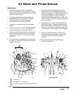
Operation
Pressure Relief Procedure
INJECTION HAZARD
The equipment stays pressurized until
pressure is manually relieved. To
reduce the risk of serious injury from
pressurized fluid, fluid from the valve or splashing
fluid, follow this procedure whenever you
D Are instructed to relieve pressure
D Stop dispensing
D Check, clean or service any system equipment
D Install or clean dispensing devices
WARNING
1. Close the pump air regulator and the bleed-type
master air valve (required in your system).
2. Hold a metal part of the dispensing valve firmly to
a grounded metal waste container and trigger the
valve to relieve the fluid pressure.
Startup
1. If there are multiple pumps on the air line, close
the air regulators and bleed-type master air valves
to all but one pump. If there is only one pump,
close its air regulator and bleed-type master air
valve.
2. Open the master air valve from the compressor.
3. Open the dispensing valve into a grounded metal
waste container, making firm metal-to-metal
contact between the container and valve. Open
the bleed-type master air valve and open the pump
air regulator slowly, just until the pump is running.
When the pump is primed and all air has been
pushed out of the lines, close the dispense valve.
4. If you have more than one pump, repeat this
procedure for each pump.
NOTE: When the pump is primed, and with sufficient
air supplied, the pump starts when the dispensing
valve is opened and shuts off when it is closed.
5. Set the air pressure to each pump at the lowest
pressure needed to get the desired results.
COMPONENT RUPTURE HAZARD
The maximum working pressure of each
component in the system may not be the
same. To reduce the risk of
overpressurizing any component in the system, be
sure you know the maximum working pressure of
each component. Never exceed the maximum
working pressure of the lowest rated component in
the system. Overpressurizing any component can
result in rupture, fire, explosion, property damage,
and serious injury.
The pump has a rated ratio of 50:1. However, it is
capable of reaching stall pressures equal to 60
times the air input pressure. Calculate the fluid
output pressure using the air regulator reading.
Multiply the air pressure shown on the regulator
gauge by 60. For example:
140 psi air x 60 = 8400 psi fluid output
0.97 MPa air x 60 = 58.2 MPa fluid output
9.7 bar air x 60 = 582 bar fluid output
Regulate air to the pump so that no air line or fluid
line component or accessory is overpressurized.
WARNING
6. Never allow the pump to run dry of the material
being pumped.
CAUTION
A dry pump will quickly accelerate to a high speed,
possibly damaging itself. If your pump accelerates
quickly, or is running too fast, stop it immediately and
check the material supply. If the supply container is
empty and air has been pumped into the lines, prime
the pump and lines with material, or flush it and leave
it filled with a compatible solvent. Be sure to elimi-
nate all air from the material lines.
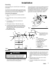
NOTE: A pump runaway valve (G) can be installed on
the air line to automatically shut off the pump if it starts
to run too fast.
7. Read and follow the instructions supplied with
each component in your system.
8. To shut off the system, always follow the Pressure
Relief Procedure at the left.