


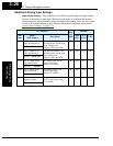

“B” Group: Fine Tuning Functions
Configuring
Drive Parameters
3–32
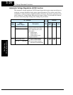
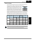
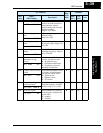
Electronic Thermal Overload Alarm Setting
The thermal overload detection protects the
inverter and motor from overheating due to
an excessive load. It uses a current/inverse
time curve to determine the trip point.
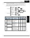
First, use B013 to select the torque charac-
teristic that matches your load. This allows
the inverter to utilize the best thermal
overload characteristic for your application.
The torque developed in a motor is directly
proportional to the current in the windings,
which is also proportional to the heat generated (and temperature, over time). Therefore,
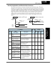
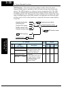
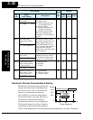
“B” Function
Run
Mode
Edit
Defaults
Func.
Code
Name /
SRW Display
Description
–FEF
(EU)
–FU
(USA)
Units
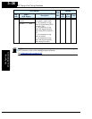
B001 Selection of automatic
restart mode
Select inverter restart method,
four option codes:
00...Alarm output after trip,
no automatic restart
01...Restart at 0Hz
02...Resume operation after
frequency matching
03...Resume previous freq.
after freq. matching, then
decelerate to stop and display
trip info.
✘ 00 00 —
IPS POWR ALM
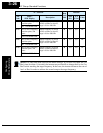
B002 Allowable under-
voltage power failure
time
The amount of time a power
input under-voltage can occur
without tripping the power
failure alarm. Range is 0.3 to
25 sec. If under-voltage exists
longer than this time, the
inverter trips, even if the restart
mode is selected.
✘ 1.0 1.0 sec.
IPS Time 0001.0s
B003 Retry wait time before
motor restart
Time delay after under-voltage
condition goes away, before
the inverter runs motor again.
Range is 0.3 to 100 seconds.
✘ 1.0 1.0 sec.
IPS Wait 0001.0s
B004 Instantaneous power
failure / under-voltage
trip alarm enable
Two option codes:
00...Disable
01...Enable
✘ 00 00 sec.
IPS TRIP OFF
B005 Number of restarts on
power failure / under-
voltage trip events
Two option codes:
00...Restart 16 times
01...Always restart
✘ 00 00 sec.
IPS RETRY 16
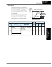
Output frequency
Constant torque
Reduced
torque
B013
=
01
B013
=
00
Tor que
520 60 120
Hz
100%
80%
60%
0