


L200 Inverter
Configuring
Drive Parameters
3–33
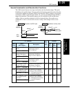
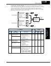
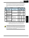
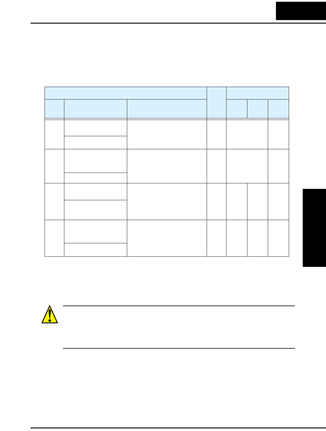
you must set the thermal overload threshold in terms of current (amperes) for parameter
B012. The range is 20% to 120% of the rated current for each inverter model. If the
current exceeds the level you specify, the inverter will trip and log an event (error E05) in
the history table. The inverter turns the motor output OFF when tripped. Separate
settings are available for the second motor (if applicable) as shown in the following
table.
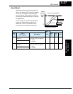
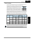
Note 1: For inverter models 005NFEF, 011NFEF, and 030HFEF, the thermal value is
less than the rated amperes (is the same as models 004NFEF, 007NFEF, and
040HFEF respectively). Therefore, be sure to set the electronic thermal
overload according to the actual motor driven by the particular inverter.
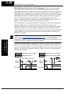
WARNING: When parameter B012, level of electronic thermal setting, is set to motor
FLA rating (Full Load Ampere nameplate rating), the inverter provides solid state motor
overload protection at 115% of motor FLA or equivalent. If parameter B012 exceeds the
motor FLA rating, the motor may overheat and be damaged. Parameter B012, level of
electronic thermal setting, is a variable parameter.
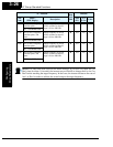
“B” Function
Run
Mode
Edit
Defaults
Func.
Code
Name /
SRW Display
Description
–FEF
(EU)
–FU
(USA)
Units
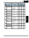
B012 Level of electronic
thermal setting
Set a level between 20% and
120% for the rated inverter
current.
✘ Rated current
for each
inverter model
*1
A
E-THM LVL001.60A
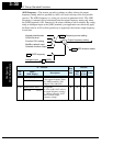
B212 Level of electronic
thermal setting, 2nd
motor
Set a level between 20% and
120% for the rated inverter
current.
✘ Rated current
for each
inverter model
*1
A
2ETHM LVL 01.60A
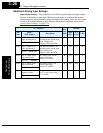
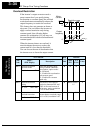
B013 Electronic thermal
characteristic
Select from two curves, option
codes:
00...Reduced torque 1
01...Constant torque
02...Reduced torque 2
✘ 01 01 —
E-THM CHAR CRT
B213 Electronic thermal
characteristic, 2nd
motor
Select from two curves, option
codes:
00...Reduced torque 1
01...Constant torque
02...Reduced torque 2
✘ 01 01 —
2ETHM CHAR CRT