


“C” Group: Intelligent Terminal Functions
Configuring
Drive Parameters
3–44
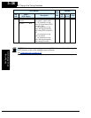
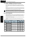
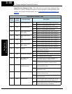
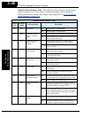
Input Function Summary Table – This table shows all twenty-four intelligent input
functions at a glance. Detailed descriptions of these functions, related parameters and
settings, and example wiring diagrams are in “
Using Intelligent Input Terminals” on
page 4–9.
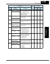
Input Function Summary Table
Option
Code
Terminal
Symbol
Function Name Description
00 FW Forward Run/Stop ON Inverter is in Run Mode, motor runs forward
OFF Inverter is in Stop Mode, motor stops
01 RV Reverse Run/Stop ON Inverter is in Run Mode, motor runs reverse
OFF Inverter is in Stop Mode, motor stops
02 CF1 *1 Multi-speed Select,
Bit 0 (LSB)
ON Binary encoded speed select, Bit 0, logical 1
OFF Binary encoded speed select, Bit 0, logical 0
03 CF2 Multi-speed Select,
Bit 1
ON Binary encoded speed select, Bit 1, logical 1
OFF Binary encoded speed select, Bit 1, logical 0
04 CF3 Multi-speed Select,
Bit 2
ON Binary encoded speed select, Bit 2, logical 1
OFF Binary encoded speed select, Bit 2, logical 0
05 CF4 Multi-speed Select,
Bit 3 (MSB)
ON Binary encoded speed select, Bit 3, logical 1
OFF Binary encoded speed select, Bit 3, logical 0
06 JG Jogging ON Inverter is in Run Mode, output to motor runs at
jog parameter frequency
OFF Inverter is in Stop Mode
07 DB External DC Braking ON DC braking will be applied during deceleration
OFF DC braking will not be applied
08 SET Set (select) 2nd
Motor Data
ON The inverter uses 2nd motor parameters for
generating frequency output to motor
OFF The inverter uses 1st (main) motor parameters
for generating frequency output to motor
09 2CH 2-stage Acceleration
and Deceleration
ON Frequency output uses 2nd-stage acceleration
and deceleration values
OFF Frequency output uses standard acceleration and
deceleration values
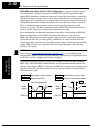
11 FRS Free-run Stop ON Causes output to turn OFF, allowing motor to
free run (coast) to stop
OFF Output operates normally, so controlled deceler-
ation stops motor
12 EXT External Trip ON When assigned input transitions OFF to ON,
inverter latches trip event and displays E12
OFF No trip event for ON to OFF, any recorded trip
events remain in history until Reset