


L200 Inverter
Operations
and Monitoring
4–11
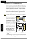
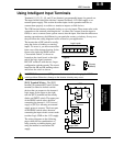
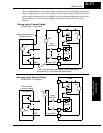
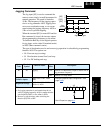
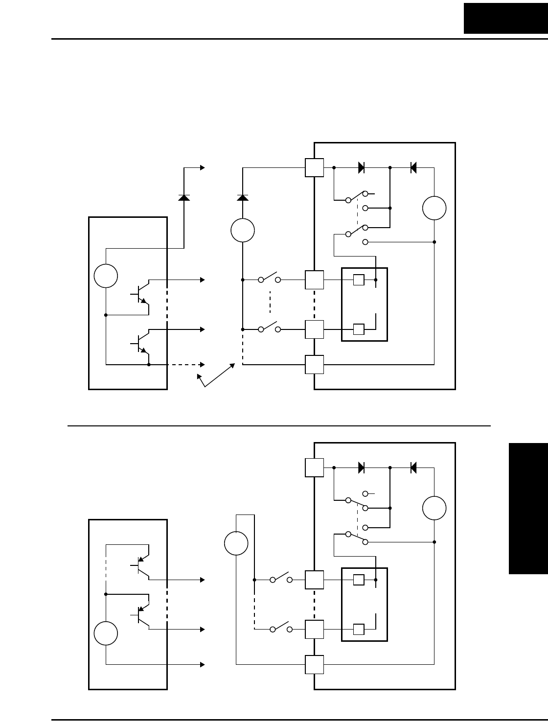
The two diagrams below show input wiring circuits using an external supply. If using the
upper wiring diagram, be sure to use a diode with the external supply. This will prevent a
power supply contention in case the SR/SK switch is accidentally placed in the incorrect
position. Be sure to use the correct SR/SK switch position shown for each wiring
diagram.
L200
L
24V
+
–
SK
SR
SK
SR
PCS
Input
circuits
1
5
Logic GND
1
5
GND
Open collector outputs,
NPN transistors
Input
switches
Sinking Inputs, External Supply
SR/SK switch = SK position
Field device
L200
L
24V
+
–
SK
SR
SK
SR
PCS
Input
circuits
1
5
1
5
GND
PNP transistor
sourcing outputs
Input
switches
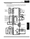
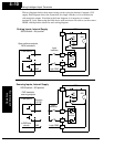
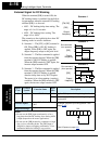
Sourcing Inputs, External Supply
SR/SK switch = SR position
Field device
Logic GND
24V
+
–
+
–
+V
**
* Note: If the external power supply GND is (optionally)
connected to [L], then install the above diode.
24V
+
–
+
–
24V