


L200 Inverter
Operations
and Monitoring
4–23
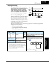
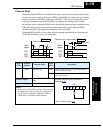
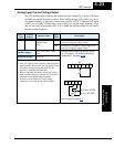
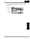
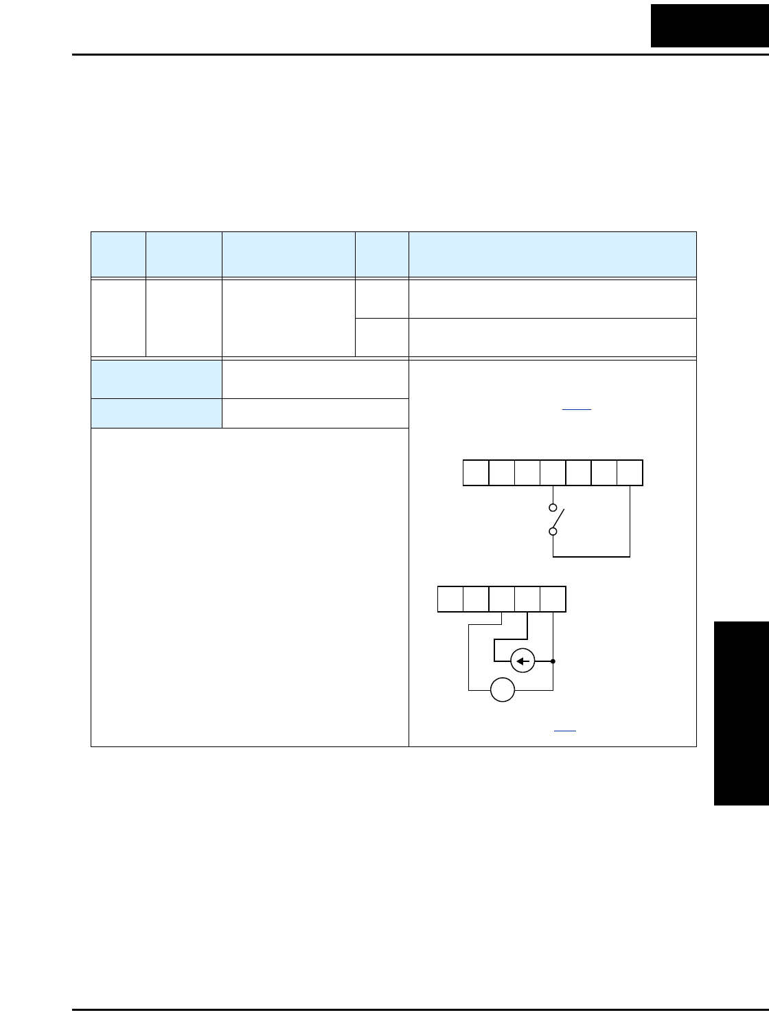
Analog Input Current/Voltage Select
The [AT] terminal selects whether the inverter uses the voltage [O] or current [OI] input
terminals for external frequency control. When intelligent input [AT] is ON, you can set
the output frequency by applying a current input signal at [OI]-[L]. When the [AT] input
is OFF, you can apply a voltage input signal at [O]-[L] to set the output frequency. Note
that you must also set parameter A001 = 01 to enable the analog terminal set for control-
ling the inverter frequency.
Option
Code
Terminal
Symbol
Function Name
Input
State
Description
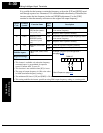
16 AT Analog Input
Voltage/current
Select
ON Terminal OI is enabled for current input (uses
terminal L for power supply return)
OFF Terminal O is enabled for voltage input (uses
terminal L for power supply return)
Valid for inputs:
C001, C002, C003, C004,
C005
Required settings:
A001 = 01
Notes:
•
If the [AT] option is not assigned to any intelligent
input terminal, then inverter uses the algebraic sum
of both the voltage and current inputs for the
frequency command (and A001=01).
• When using either the analog current and voltage
input terminal, make sure that the [AT] function is
allocated to an intelligent input terminal.
• Be sure to set the frequency source setting
A001=01 to select the analog input terminals.
Example (default input configuration shown
for –FU models; –FE models require input
configuration—see page 3–42
):
See I/O specs on page 4–6
.
AT
12345L
PCS
+ –
4-20 mA, AT=ON
0-10 V, AT=OFF
LH O
OIAM