


Using Intelligent Input Terminals
Operations
and Monitoring
4–26
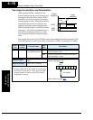
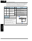
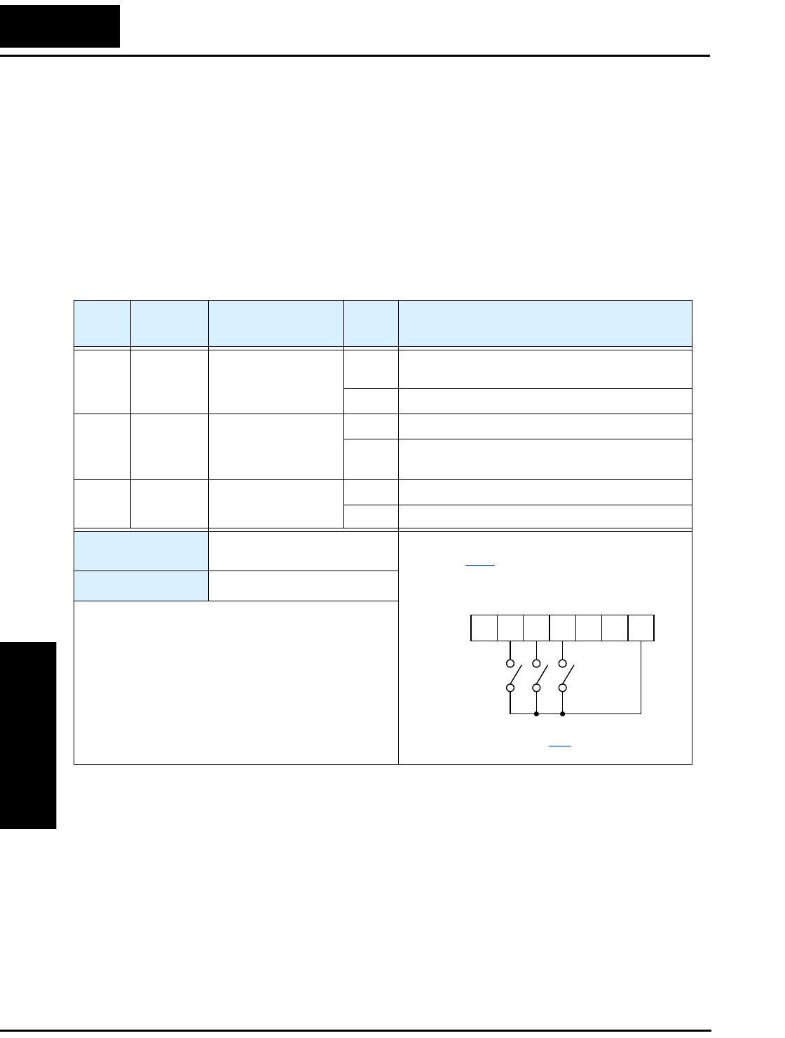
Three-wire Interface Operation
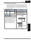
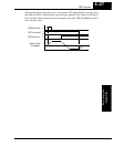
The 3-wire interface is an industry standard motor control interface. This function uses
two inputs for momentary contact start/stop control, and a third for selecting forward or
reverse direction. To implement the 3-wire interface, assign 20 [STA] (Start), 21 [STP]
(Stop), and 22 [F/R] (Forward/Reverse) to three of the intelligent input terminals. Use a
momentary contact for Start and Stop. Use a selector switch, such as SPST for the
Forward/Reverse input. Be sure to set the operation command selection A002=01 for
input terminal control of motor.
If you have a motor control interface that needs logic-level control (rather than momen-
tary pulse control), use the [FW] and [RV] inputs instead.
Option
Code
Terminal
Symbol
Function Name
Input
State
Description
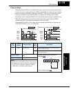
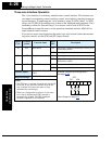
20 STA Start Motor ON Start motor rotation on momentary contact (uses
acceleration profile)
OFF No change to motor operation
21 STP Stop Motor ON No change to motor operation
OFF Stop motor rotation on momentary contact (uses
deceleration profile)
22 F/R Forward/Reverse ON Select reverse direction of rotation
OFF Select forward direction of rotation
Valid for inputs:
C001, C002, C003, C004,
C005
Required settings:
A002 = 01
Notes:
•
The STP logic is inverted. Normally the switch will
be closed, so you open the switch to stop. In this
way, a broken wire causes the motor to stop
automatically (safe design).
• When you configure the inverter for 3-wire inter-
face control, the dedicated [FW] terminal is
automatically disabled. The [RV] intelligent
terminal assignment is also disabled.
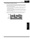
Example (requires input configuration—
see page 3–42
):
See I/O specs on page 4–6
.
STP
STAF/R
12345L
PCS