


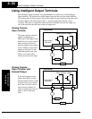
Using Intelligent Output Terminals
Operations
and Monitoring
4–38
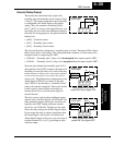
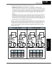
Frequency Arrival Signals
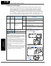
The Frequency Arrival group of outputs help coordinate external systems with the
current velocity profile of the inverter. As the name implies, output [FA1] turns ON
when the output frequency arrives at the standard set frequency (parameter F001).
Output [FA2] relies on programmable accel/ decel thresholds for increased flexibility.
For example, you can have an output turn ON at one frequency during acceleration, and
have it turn OFF at a different frequency during deceleration. All transitions have hyster-
esis to avoid output chatter if the output frequency is near one of the thresholds.
Option
Code
Terminal
Symbol
Function Name
Output
State
Description
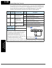
01 FA1 Frequency Arrival
Type 1 – Constant
Speed
ON when output to motor is at the set frequency
OFF when output to motor is OFF, or in any accelera-
tion or deceleration ramp
02 FA2 Frequency Arrival
Type 2 – Over-
frequency
ON when output to motor is at or above the set
frequency thresholds for, even if in acceleration
or deceleration ramps
OFF when output to motor is OFF, or during accelera-
tion or deceleration before the respective thresh-
olds are crossed
Valid for outputs:
11, 12, AL0 – AL2
Required settings:
(none)
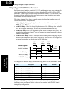
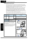
Notes:
•
For most applications you will need to use only one
type of frequency arrival outputs (see examples).
However, it is possible assign both output terminals
to output functions [FA1] and [FA2].
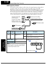
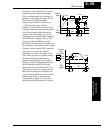
• For each frequency arrival threshold, the output
anticipates the threshold (turns ON early) by 1.5Hz.
• The output turns OFF as the output frequency
moves away from the threshold, delayed by 0.5Hz.
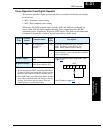
• The delay time of the output signal is 60 ms
(nominal).
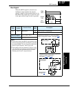
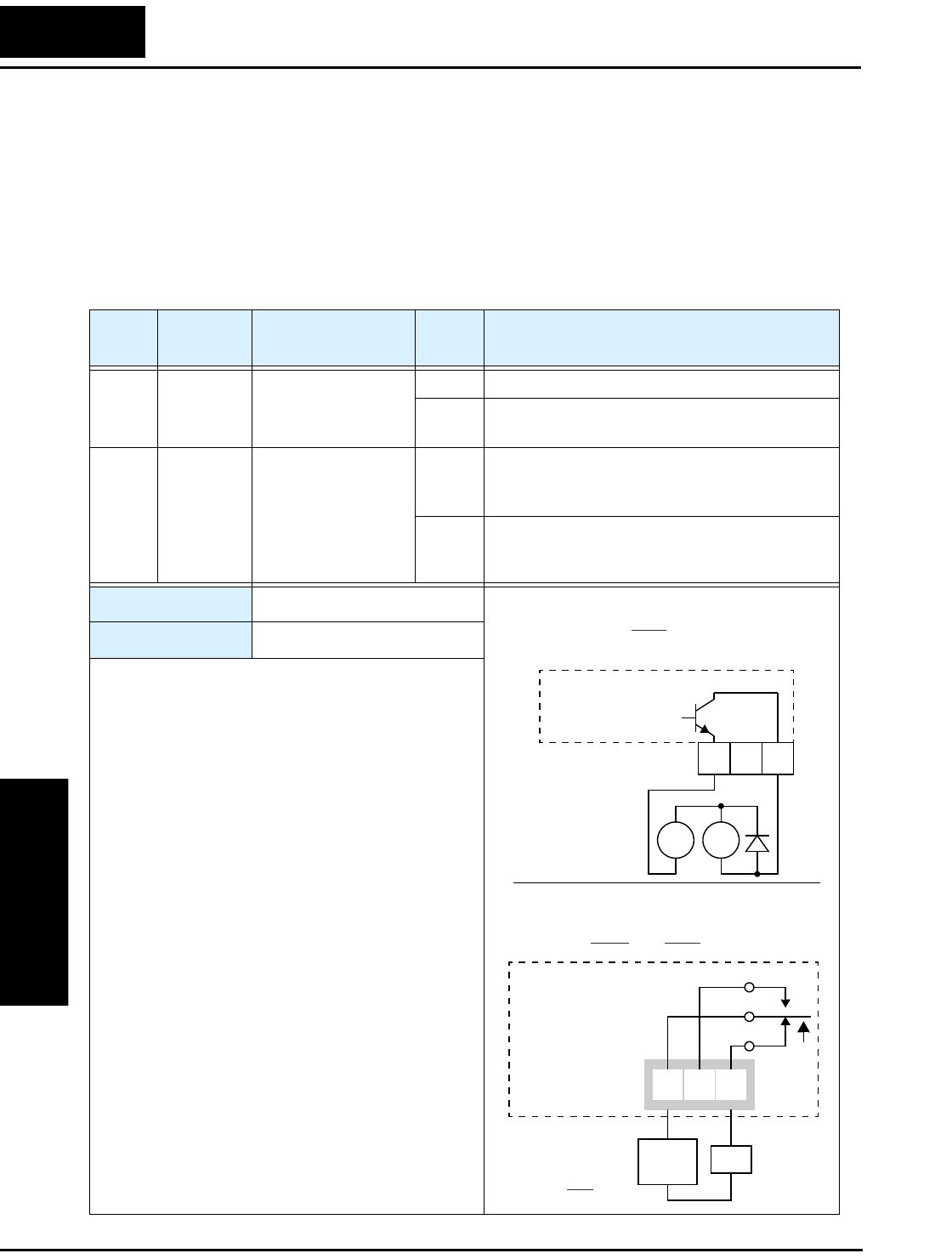
• The example circuit for terminal [12] drives a relay
coil. Note the use of a diode to prevent the negative-
going turn-off spike generated by the coil from
damaging the inverter’s output transistor.
Example (default output configuration
shown—see page 3–47
):
Inverter output
terminal circuit
RY
+
–
FA1
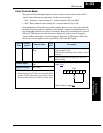
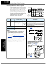
Example for terminals [AL0], [AL1], [AL2]
(requires output configuration—
see pages
4–35 and 3–47):
AL0
AL2AL1
Inverter logic
circuit board
See I/O specs
on page 4–6
.
FA1
Load
Power
supply
12 11
CM2