


Using Intelligent Output Terminals
Operations
and Monitoring
4–40
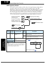
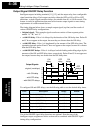
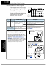
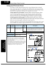
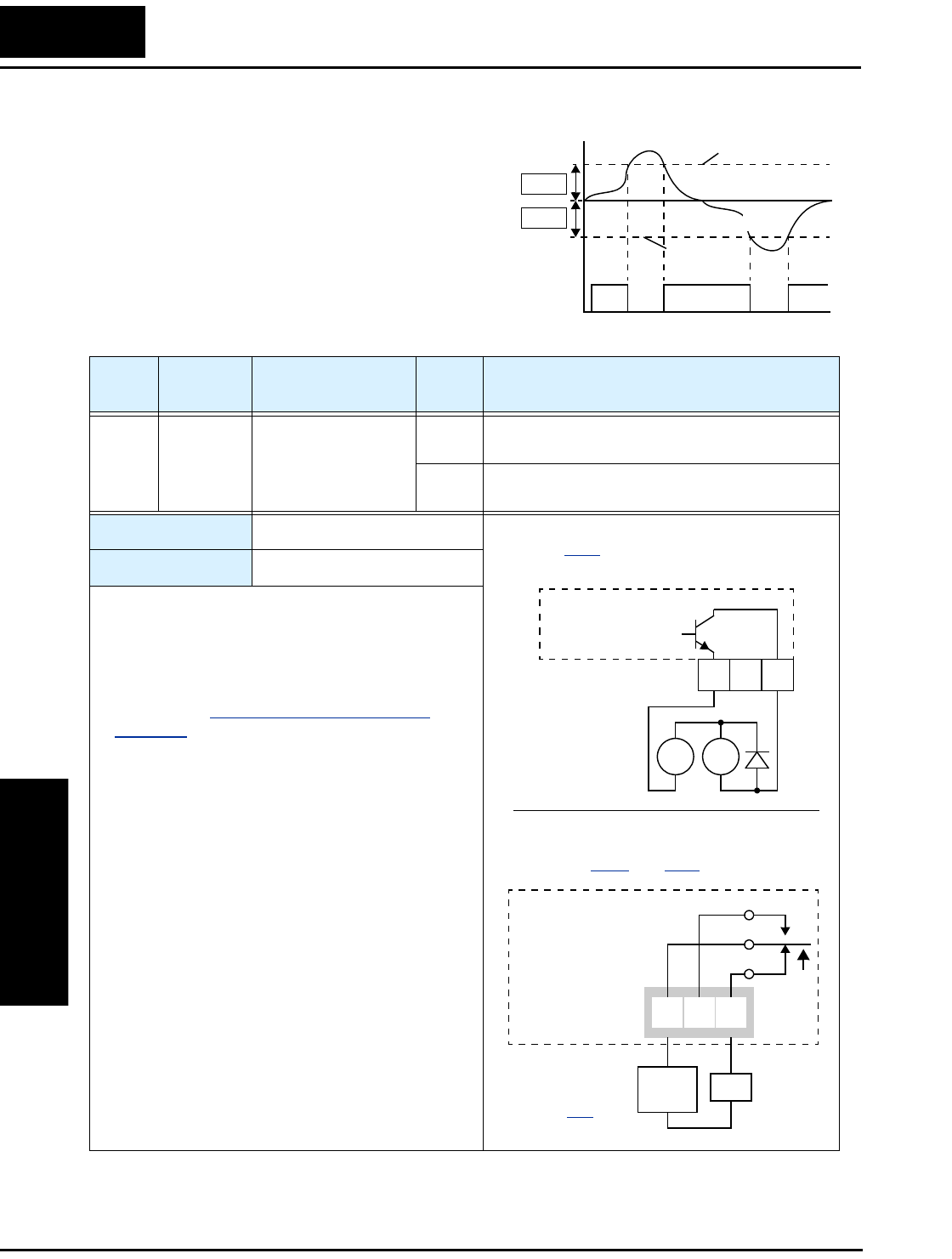
Overload Advance Notice Signal
When the output current exceeds a preset
value, the [OL] terminal signal turns ON.
The parameter C041 sets the overload
threshold. The overload detection circuit
operates during powered motor opera-
tion and during regenerative braking. The
output circuits use open-collector
transistors, and are active low.
[OL]
Signal
1
0
ON
t
ON
Current
threshold
regeneration
power running
threshold
C041
C041
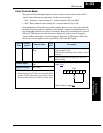
Option
Code
Terminal
Symbol
Function Name
Output
State
Description
03 OL Overload Advance
Notice Signal
ON when output current is more than the set thresh-
old for the overload signal
OFF when output current is less than the set threshold
for the overload signal
Valid for outputs:
11, 12, AL0 – AL2
Required settings:
C041
Notes:
•
The default value is 100%. To change the level
from the default, set C041 (overload level).
• The accuracy of this function is the same as the
function of the output current monitor on the [FM]
terminal (see “
Analog Output Operation” on
page 4–53).
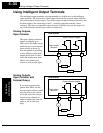
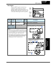
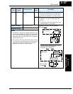
• The example circuit for terminal [12] drives a relay
coil. Note the use of a diode to prevent the negative-
going turn-off spike generated by the coil from
damaging the inverter’s output transistor.
RY
+
–
Example (requires output configuration—
see page 3–47
):
Inverter output
terminal circuit
OL
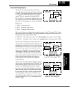
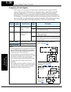
Example for terminals [AL0], [AL1], [AL2]
(requires output configuration—
see pages
4–35 and 3–47):
AL0 AL2AL1
Inverter logic
circuit board
See I/O specs
on page 4–6
.
OL
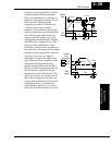
Load
Power
supply
12 11
CM2