


Using Intelligent Output Terminals
Operations
and Monitoring
4–46
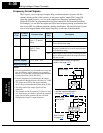
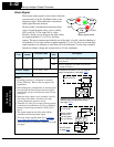
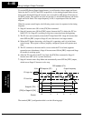
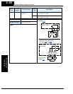
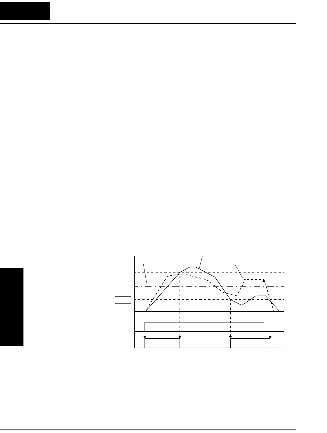
To use the PID Second Stage Output feature, you will need to choose upper and lower
limits for the PV, via C053 and C052 respectively. As the timing diagram below shows,
these are the thresholds Stage #1 inverter uses to turn ON or OFF Stage #2 inverter via
the [FBV] output. The vertical axis units are percent (%) for the PID setpoint, and for the
upper and lower limits. The output frequency, in Hz, is superimposed onto the same
diagram.
When the system control begins, the following events occur (in sequence in the timing
diagram):
1. Stage #1 inverter turns ON via the [FW] Run command.
2. Stage #1 inverter turns ON the [FBV] output, because the PV is below the PV low
limit C053. So, Stage #2 is assisting in loop error correction from the beginning.
3. The PV rises and eventually exceeds the PV high limit C052. Stage #1 inverter then
turns OFF the [FBV] output to Stage #2, since the boost is no longer needed.
4. When the PV begins decreasing, only Stage #1 is operating, and it is in the linear
control range. This region is where a properly configured system will operate most
often.
5. The PV continues to decrease until it crosses under the PV low limit (apparent
external process disturbance). Stage #1 inverter turns ON the [FBV] output, and Stage
#2 inverter is assisting again.
6. After the PV rises above the PV low limit, the [FW] Run command to Stage #1
inverter turns OFF (as in a system shutdown).
7. Stage #1 inverter enters Stop Mode and automatically turns OFF the [FBV] output,
which causes Stage #2 inverter to also stop.
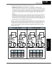
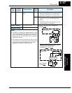
The terminal [FBV] configuration table is on the following page.
%/Hz
[FBV] to Stage #2 [FW]
Stage #1 [FW]
1
0
t
1
0
C053
C052
PV high limit
PV low limit
PID feedback (PV)
Output frequency
Events:
1,2 3 4 5 6 7
PID setpoint (SP)