


L200 Inverter
Operations
and Monitoring
4–47
Option
Code
Terminal
Symbol
Function Name
Output
State
Description
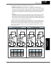
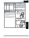
07 FBV Feedback Value
Check
ON
• Transitions to ON when the inverter is in RUN
Mode and the PID Process Variable (PV) is
less than the Feedback Low Limit (C053)
OFF
• Transitions to OFF when the PID Feedback
Value (PV) exceeds the PID High Limit
(C052)
• Transitions to OFF when the inverter goes
from Run Mode to Stop Mode
Valid for outputs:
11, 12, AL0 – AL2
Required settings:
A076, C052, C053
Notes:
•
The [FBV] is designed for implementing two-stage
control. The PV high limit and PV low limit param-
eters, C052 and C053, do not function as process
alarm thresholds. Terminal [FBV] does not provide
a PID alarm function.
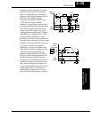
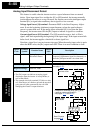
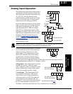
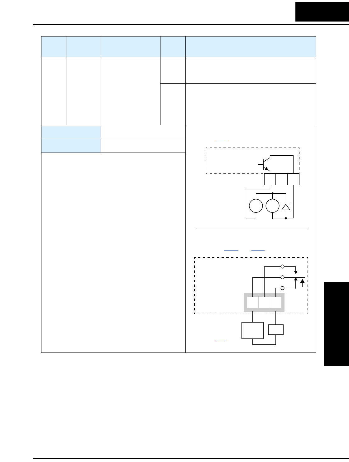
• The example circuit for terminal [12] drives a relay
coil. Note the use of a diode to prevent the negative-
going turn-off spike generated by the coil from
damaging the inverter’s output transistor.
RY
+
–
Example (requires output configuration—
see page 3–47
):
Inverter output
terminal circuit
FBV
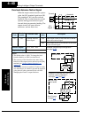
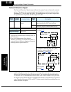
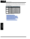
Example for terminals [AL0], [AL1], [AL2]
(requires output configuration—
see pages
4–35 and 3–47):
AL0
AL2AL1
Inverter logic
circuit board
See I/O specs
on page 4–6
.
FBV
Load
Power
supply
12 11
CM2