


L200 Inverter
Operations
and Monitoring
4–55
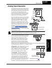
PID Loop Configuration
The inverter’s PID loop algorithm is configurable for various applications.
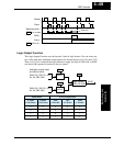
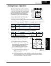
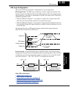
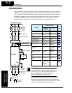
PID Output Limit - The PID loop controller has a built-in output limit function. This
function monitors the difference between the PID setpoint and the loop output (inverter
output frequency), measured as a percentage of the full scale range of each. The limit is
specified by parameter A078.
• When the difference |(Setpoint – loop output)| is smaller than or equal to the A078
limit value, the loop controller operates in its normal linear range.
• When the difference |(Setpoint – loop output)| is larger than the A078 limit value, the
loop controller changes the output frequency as needed so that the difference does not
exceed the limit.
The diagram below shows PID setpoint changes and the related output frequency
behavior when a limit value in A078 exists.
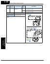
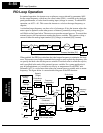
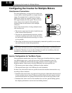
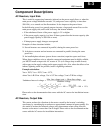
Error Inversion - In typical heating loops or ventilation loops, an increase in energy
into the process results in an increasing PV. In this case, the Loop Error = (SP – PV). For
cooling loops, an increase in energy into the process results in a decreasing PV. In this
case, the Loop Error = –(SP – PV). Use A077 to configure the error term.
Other PID-related topics:
• “
PID Control” on page 3–23
• “PID ON/OFF and PID Clear” on page 4–28
• “Output Deviation for PID Control” on page 4–41
• “PID Second Stage Output” on page 4–45
Limit value
PID Setpoint
t
A078
Limit value
A078
Output limit
Output limit
%
Limit imposed
on output
Limit imposed
on output
Output frequency
∑
PID
Calculation
SP Error Freq.
PV from process with
positive correlation
PV
+
–
A077 = 00
∑
PID
Calculation
SP Error Freq.
PV from process with
negative correlation
PV
–
+
A077 = 01