


L200 Inverter
Operations
and Monitoring
4–57
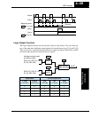
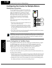
Having two motor profiles lets you store two “personalities” for motors in one inverter’s
memory. The inverter allows the final selection between the two motor types to be made
in the field through the use of an intelligent input terminal function [SET]. This provides
an extra level of flexibility needed in particular situations. See the following table.
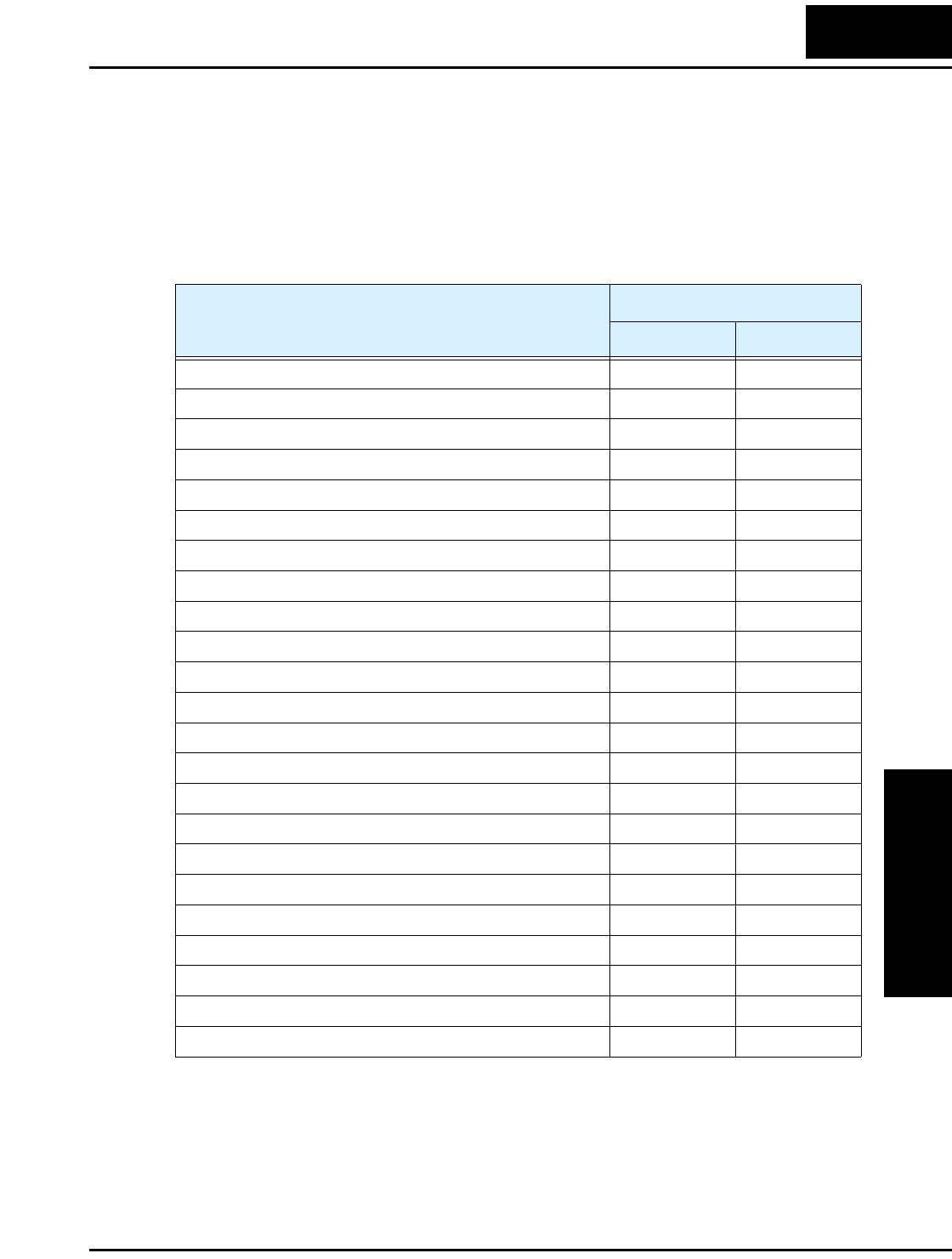
Parameters for the second motor have a function code of the form x2xx. They appear
immediately after the first motor’s parameter in the menu listing order. The following
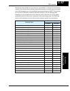
table lists the parameters that have the second parameter register for programming.
Function Name
Parameter Codes
1st motor 2nd motor
Multi-speed frequency setting A020 A220
Acceleration (1) time setting F002 F202
Deceleration (1) time setting F003 F203
Acceleration (2) time setting A092 A292
Deceleration (2) time setting A093 A293
Select method to use Acc2/Dec2 A094 A294
Acc1 to Acc2 frequency transition point A095 A295
Dec1 to Dec2 frequency transition point A096 A296
Level of electronic thermal setting B012 B212
Electronic thermal characteristic B013 B213
Torque boost select A041 A241
Manual torque boost value A042 A242
Manual torque boost frequency adjustment A043 A243
V/f characteristic curve selection A044 A244
iSLV voltage gain A046 A246
iSLV slip compensation A047 A247
Base frequency setting A003 A203
Maximum frequency setting A004 A204
Frequency upper limit setting A061 A261
Frequency lower limit setting A062 A262
Motor capacity H003 H203
Motor poles setting H004 H204
Motor stabilization constant H006 H206