


Introduction
Motor Control
Accessories
5–2
Introduction
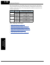
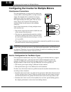
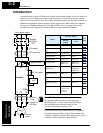
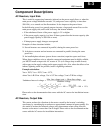
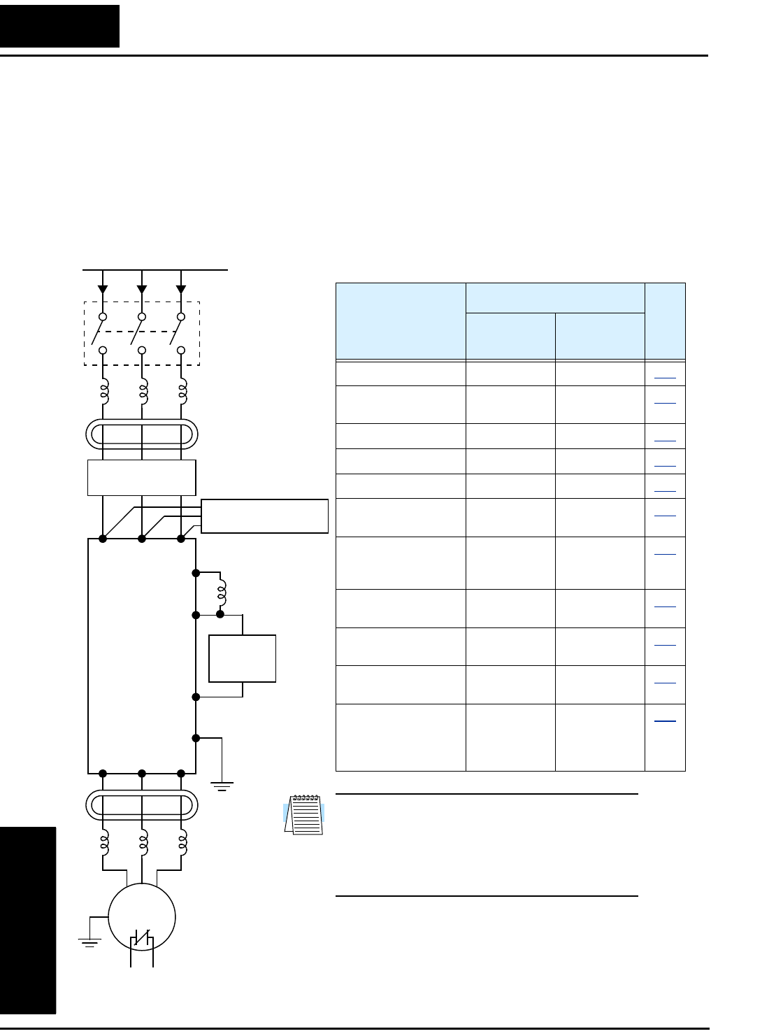
A motor control system will obviously include a motor and inverter, as well as fuses for
safety. If you are connecting a motor to the inverter on a test bench just to get started,
that’s all you may need for now. But a fully developed system can also have a variety of
additional components. Some can be for noise suppression, while others may enhance
the inverter’s braking performance. The figure below shows a system with several
possible optional components, and the table gives part number information.
Thermal
switch
Breaker,
MCCB or
GFI
From power supply
Motor
L1 L2 L3
+1
+
Inverter
GND
T1 T2 T3
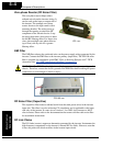
Note: The Hitachi part number series for accesso-
ries includes different sizes of each part type,
specified by the –x suffix. Hitachi product litera-
ture can help match size and rating of your
inverter to the proper accessory size.
Each inverter accessory comes with its own printed
instruction manual. Please refer to those manuals for
complete installation details. This chapter gives only an
overview of these optional system devices.
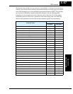
Name
Part No. Series
See
page
Europe,
Japan
USA
AC reactor, input side ALI–xxx2 HRL–x
5–3
RF noise filter, input
side
ZCL–xxx ZCL–xxx
5–4
EMI filter (for CE) FFL100–xxx FFL100–xxx
5–4
Capacitive filter CFI–x CFI–x
5–4
DC link choke DCL–x–xx HDC–xxx
5–4
Braking resistor JRB–xxx–x
SRB–xxx–x
JRB–xxx–x
SRB–xxx–x
5–5
Braking resistor,
NEMA-rated
—HRB-x,
NSRBx00–x
NJRB–xxx
5–5
Resistance braking
unit
BRD–xxx BRD–xxx
5–5
RF noise filter, output
side
ZCL–xxx ZCL–xxx
5–4
AC reactor, output
side
ALI–x2–xxx HRL–xxx
5–3
LCR filter Combination:
ALI–x2–xxx
LPF–xxx
R–2–xxx
HRL–xxC
5–3
AC reactor
RF noise filter
EMI filter
Capacitive filter
–
DC link choke
Braking
unit
RF noise
filter
AC reactor, or
LCR filter