


L200 Inverter
Motor Control
Accessories
5–3
Component Descriptions
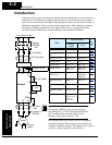
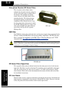
AC Reactors, Input Side
This is useful in suppressing harmonics induced on the power supply lines, or when the
main power voltage imbalance exceeds 3% (and power source capacity is more than
500 kVA), or to smooth out line fluctuations. It also improves the power factor.
In the following cases for a general-purpose inverter, a large peak current flows on the
main power supply side, and is able to destroy the inverter module:
• If the unbalanced factor of the power supply is 3% or higher
• If the power supply capacity is at least 10 times greater than the inverter capacity (the
power supply capacity is 500 kVA or more)
• If abrupt power supply changes are expected
Examples of these situations include:
1. Several inverters are connected in parallel, sharing the same power bus
2. A thyristor converter and an inverter are connected in parallel, sharing the same
power bus
3. An installed phase-advance (power factor correction) capacitor opens and closes
Where these conditions exist or when the connected equipment must be highly reliable,
you MUST install an input-side AC reactor of 3% (at a voltage drop at rated current)
with respect to the supply voltage on the power supply side. Also, where the effects of an
indirect lightning strike are possible, install a lightning conductor.
Example calculation:
V
RS
= 205V, V
ST
= 203V, V
TR
= 197V,
where V
RS
is R-S line voltage, V
ST
is S-T line voltage, V
TR
is T-R line voltage
Please refer to the documentation that comes with the AC reactor for installation instruc-
tions.
AC Reactors, Output Side
This reactor reduces the vibrations in the motor caused by the inverter’s switching
waveforms, by smoothing the waveforms to approximate commercial power quality. It is
also useful to reduce the reflected voltage wave phenomenon when wiring from the
inverter to the motor is more than 10m in length. Please refer to the documentation that
comes with the AC reactor for installation instructions.
Unbalance factor of voltage
Max. line voltage (min.) Mean line voltage–
Meanline voltage
-----------------------------------------------------------------------------------------------------------
100×=
V
RS
V
RS
V
ST
V
TR
++()3⁄–
V
RS
V
ST
V
TR
++()3⁄
-------------------------------------------------------------------
100×=
205 202–
202
------------------------
100× 1.5%==