


L200 Inverter
Motor Control
Accessories
5–5
Dynamic Braking
Introduction
The purpose of dynamic braking is to improve the ability of the inverter to stop (deceler-
ate) the motor and load. This becomes necessary when an application has some or all of
the following characteristics:
• High load inertia compared to the available motor torque
• The application requires frequent or sudden changes in speed
• System losses are not great enough to slow the motor as needed
When the inverter reduces its output frequency to decelerate the load, the motor can
temporarily become a generator. This occurs when the motor rotation frequency is
higher than the inverter output frequency. This condition can cause the inverter DC bus
voltage to rise, resulting in an over-voltage trip. In many applications, the over-voltage
condition serves as a warning signal that we have exceeded the deceleration capabilities
of the system. The L200 inverter can connect to an external braking unit, which sends
the regenerative energy from the motor during deceleration to the optional braking resis-
tor(s). The dynamic braking resistor serves as a load, developing heat to stop the motor
just as brakes on an automobile develop heat during braking.
A switching circuit and power resistor are the main components of the dynamic braking
unit that includes a fuse and thermally activated alarm relay for safety. However, be
careful to avoid overheating its resistor. The fuse and thermal relay are safeguards for
extreme conditions, but the inverter can maintain braking usage in a safe zone.
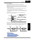
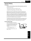
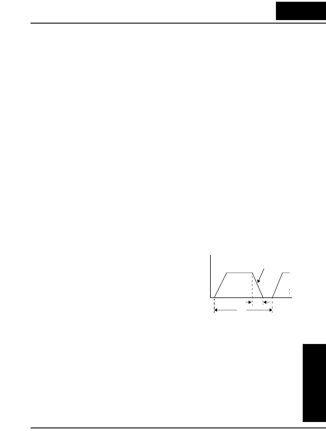
Dynamic Braking Usage
Dynamic braking usage must follow guide-
lines to avoid overheating. The timing diagram
to the right shows the output frequency versus
time. Dynamic braking is in effect during the
deceleration ramp, and has the following
constraints:
• Dynamic braking maximum duty cycle
= 10%, where T
b
/T
c
≤ 0.1 sec.
Dynamic braking maximum continuous ON
time T
b
≤ 10 sec.
Output
freq.
T
b
t
T
c
Dynamic braking