


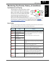


L200 Inverter
Troubleshooting
and Maintenance
6–13
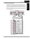
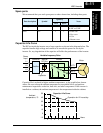
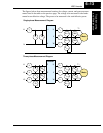
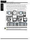
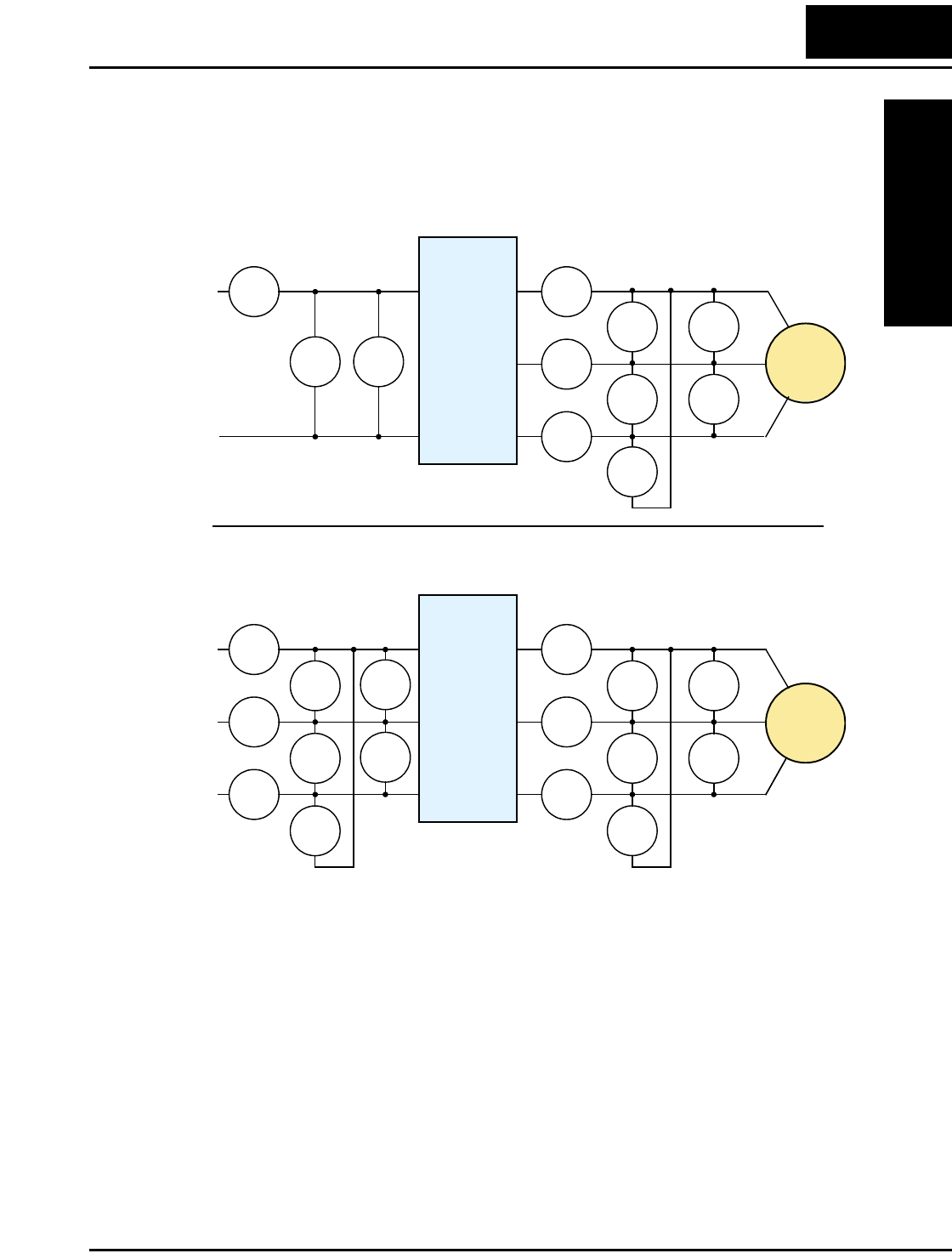
The figures below show measurement locations for voltage, current, and power measure-
ments listed in the table on the previous page. The voltage to be measured is the funda-
mental wave effective voltage. The power to be measured is the total effective power.
E
1
W
1
I
1
I
1
I
1
I
1
E
U-V
E
U-V
E
U-V
W
01
W
02
E
1
I
1
I
1
I
1
I
1
E
U-V
E
U-V
E
U-V
W
01
W
02
W
01
W
02
E
1
E
1
I
2
I
3
Single-phase Measurement Diagram
Three-phase Measurement Diagram
L1
N
L1
N
U
V
W
T1
T2
T3
Inverter
Motor
T1
T2
T3
U
V
W
R
S
T
Inverter
Motor
L1
L2
L3