


L200 Inverter
Appendix B
B–21
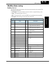
ModBus Holding Registers
The following tables list the holding registers for the inverter interface to the network.
The table legend is given below.
• Function Code - The inverter’s reference code for the parameter or function (same as
inverter keypad display)
• Name - The standard functional name of the parameter or function for the inverter
• R/W - The read-only or read-write access permitted to the data in the inverter
• Description - How the parameter or setting works (same as Chapter 3 description).
• Reg. - The network register address to the value (some values have a high-byte and
low-byte address)
• Range - The numerical range for the network value that is sent and/or received
TIP: The network values are binary integers. Since these values cannot have an
embedded decimal point, for many parameters it represents the actual value (in engineer-
ing units) multiplied by a factor of 10 or 100. Network communications must use the
listed range for network data. The inverter automatically divides received values by the
appropriate factor in order to establish the decimal point for internal use. Likewise, the
network host computer must apply the same factor when it needs to work in engineering
units. However, when sending data to the inverter, the network host computer must scale
values to the integer range listed for network communications.
• Resolution - This is the quantity represented by the LSB of the network value, in
engineering units. When the network data range is greater than the inverter’s internal
data range, this 1-bit resolution will be fractional.
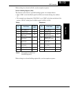
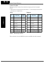
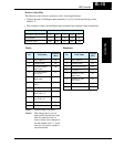
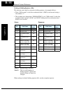
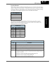
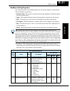
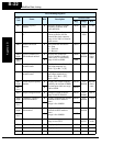
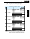
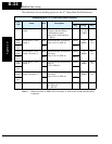
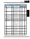
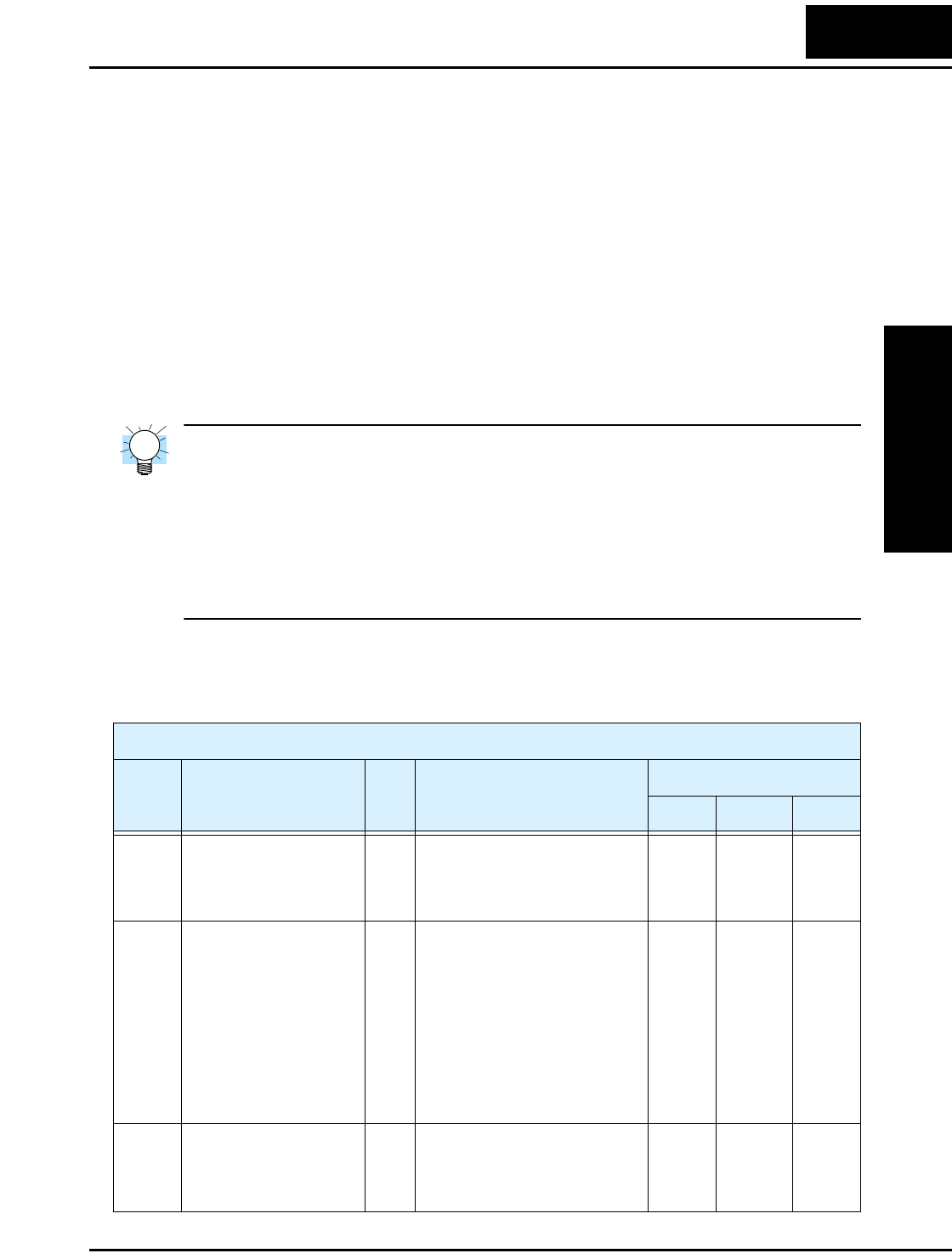
List of Holding Registers
Func.
Code
Name R/W Description
Network Data
Reg. Range Res.
— Output frequency
command
Inverter output frequency (set
A001=03 to enable this
network register),
range is 0.0 to 400.0 Hz
001h 0 to
4000
0.1 Hz
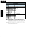
— Inverter status R/W 00...Initial status
01...(Reserved)
02...Stop Mode
03...Run Mode
04...Free-run stop (FRS)
05...Jogging
06...DC braking
07...Retry
08...Trip alarm
09...Under-voltage
002h 0 to 9 —
— Process Variable (PV) PID loop PV value from the
network (set A076=02 to
enable this setting), range is
0.0 to 100.0%
003h 0 to
1000
0.1%