


L200 Inverter
Appendix B
B–25
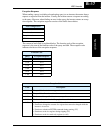
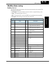
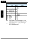
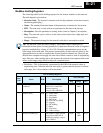
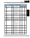
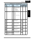
The following table lists the holding registers for the “A” Group Standard Functions.
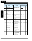
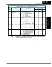
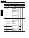
Holding Registers for “A” Group Standard Functions
Func.
Code
Name R/W Description
Network Data
Reg. Range Res.
A001 Frequency source
setting
R/W Five options; select codes:
00...Keypad potentiometer
01...Control terminal
02...Function F001 setting
03...ModBus network input
10...Calculate function output
002Dh 0 to 3, 10 —
A002 Run command source
setting
R/W Three options; select codes:
01...Control terminal
02...Run key on keypad, or
digital operator
03...ModBus network input
002Eh 1, 2, 3 —
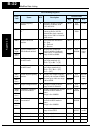
A003 Base frequency setting R/W Settable from 30 Hz to the
maximum frequency
002Fh 30 to
max. freq.
1 Hz
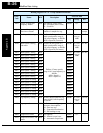
A203 Base frequency setting,
2nd motor
R/W Settable from 30 Hz to the 2nd
maximum frequency
0030h 30 to
max. freq.
2
1 Hz
A004 Maximum frequency
setting
R/W Settable from the base
frequency up to 400 Hz
0031h 30 to 400 1 Hz
A204 Maximum frequency
setting, 2nd motor
R/W Settable from the 2nd base
frequency up to 400 Hz
0032h 30 to 400 1 Hz
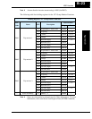
A005 [AT] selection R/W Four options, select codes:
00...Select between [O] and
[OI] at [AT]
01...[O] + [OI] ([AT] input is
ignored)
02...Select between [O] and
keypad potentiometer
03...Select between [OI] and
keypad potentiometer
0033h 0, 1, 2, 3 —
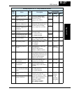
A011 Pot./O–L input active
range start frequency
R/W The output frequency corre-
sponding to the analog input
range starting point,
range is 0.0 to 400.0
0034h 0 to 4000 0.1 Hz
A012 Pot./O–L input active
range end frequency
R/W The output frequency corre-
sponding to the analog input
range ending point,
range is 0.0 to 400.0
0035h 0 to 4000 0.1 Hz
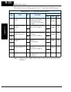
A013 Pot./O–L input active
range start voltage
R/W The starting point (offset) for
the active analog input range,
range is 0. to 100
0036h 0 to 100 1 %
A014 Pot./O–L input active
range end voltage
R/W The ending point (offset) for
the active analog input range,
range is 0. to 100.
0037h 0 to 100 1 %