


Index–2
Choke 2–7, 5–4, A–2
Chopper frequency 3–38
Circuit breaker sizes xiv
Clearance for ventilation 2–10
Coasting 3–40
Connectors
logic terminals 2–4
removal 2–4
serial port B–3
Constant torque 3–17
Constant volts/hertz operation 1–13
Contact information xviii
Control algorithms 3–17
Copy unit 1–3, 3–2
Cover removal 2–3
Current calculation 3–37
Current input 3–14
Current overload 2–29, 3–34
Current/voltage analog input select 4–23
D
D Group parameters 3–6
DC braking 3–20, 4–15, 4–16, A–3
Deadband A–3
Deceleration 1–16, 3–9, 4–15
characteristic curves 3–27
second function 3–25
two-stage 4–18
Default settings
listing C–2
restoring 6–8
Delay function, output circuits 3–55, 4–36
Derivative gain 3–23
Digital operator 1–3, 2–23, 3–3, A–3
Dimensions
inverter 2–11
terminals 2–17
Diode A–3
DIP switch configuration 2–5, 2–26, 3–11, 4–
9, B–4
Disconnect detect, analog input 4–44
Duty cycle A–3
Dynamic braking 1–15, 5–5, A–3
usage 5–5
E
Editing parameters 2–23, 2–26
in Run Mode 3–5, 3–35, 4–22
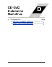
Electromagnetic compatibility D–2
Electronic thermal overload xiv
configuration 3–32
error code 6–5
EMC installation
guidelines D–2
recommendations D–6
EMI A–3
EMI filter xi, 5–4
Environmental specs 1–10
Error codes, trip events 6–5
Error, PID loop 4–41, A–3
Event clearing 4–24
External trip 4–20
error code 6–6
F
F Group functions 3–9
Factory default settings 3–38
restoring 6–8
Fan outlet 2–10, 2–21
FAQ 1–17
Features 1–2, 2–2
Filters, noise suppression 5–2
Fine-tuning functions 3–31
Force operation from digital operator 4–31
Force terminal mode 4–33
Forward run command 4–12
Four-quadrant operation A–3
Free-run stop 3–40, 4–15, 4–19, A–4
Frequency arrival signals 4–38
Frequency display scaling 3–38
Frequency limits 3–21
Frequency matching 3–40
Frequency setting A–4
Frequency source setting 3–10, 4–31, 4–33
Frequency-related functions 3–21
Frequently asked questions 1–17
Functions 1–15, 2–24
Fuse sizes xiv, 2–16