


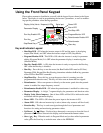
Using the Front Panel Keypad
Inverter Mounting
and Installation
2–30
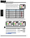
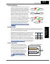
Set the Number of Motor Poles - The motor’s internal winding arrangement deter-
mines its number of magnetic poles. The specifications label on the motor usually
indicates the number of poles. For proper operation, verify the parameter setting matches
the motor poles. Many industrial motors have four poles, corresponding to the default
setting in the inverter (H004).
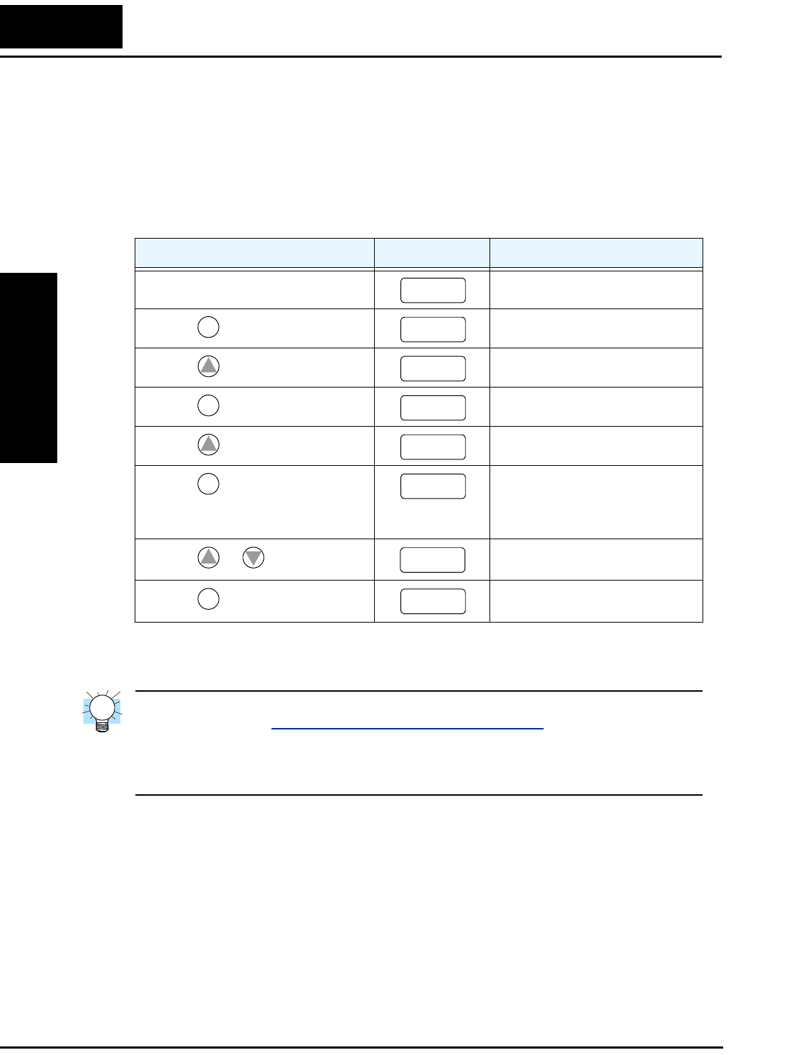
Follow the steps in the table below to verify the motor poles setting and change it if
necessary (the table resumes action from the end of the previous table).
This step concludes the parameter setups for the inverter. You are almost ready to run the
motor for the first time!
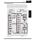
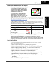
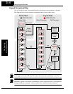
TIP: If you became lost during any of these steps, first observe the state of the PRG
LED. Then study the “
Keypad Navigational Map” on page 2–25 to determine the current
state of the keypad controls and display. As long as you do not press the STR key, no
parameters will be changed by keypad entry errors. Note that power cycling the inverter
causes it to power up Monitor Mode, displaying the value for D001 (output frequency).
The next section will show you how to monitor a particular parameter from the display.
Then you will be ready to run the motor.
Action Display Func./Parameter
(Starting point)
Level of electronic thermal setting
Press the
key.
“B” Group selected
Press the
key two times.
“H” Group selected
Press the
key.
First “H” parameter
Press the
key once.
Motor poles parameter
Press the
key.
2 = 2 poles
4 = 4 poles (default)
6 = 6 poles
8 = 8 poles
Press the
or key as needed.
Set to match your motor (your
display may be different)
Press the
key.
Stores parameter, returns to “H”
Group list
b
01 2
FUNC.
b
–––
1
H– – –
FUNC.
H003
1
H004
FUNC.
4
1
2
4
STR
H004