


“A” Group: Standard Functions
Configuring
Drive Parameters
3–10
“A” Group: Standard Functions
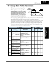
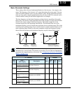
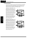
Control Source Settings
The inverter provides flexibility in how you control Run/Stop operation and set the
output frequency (motor speed). It has other control sources that can override the A001/
A002 settings. Parameter A001 sets the source selection for the inverter’s output
frequency. Parameter A002 selects the Run command source (for FW or RV Run
commands). The default settings use the input terminals for –FEF (European) models,
and the keypad for –FU (USA) models.
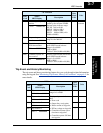
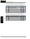
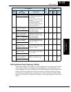
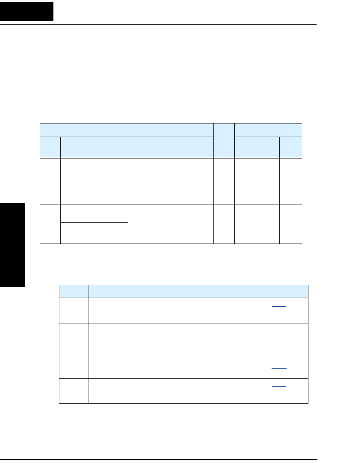
Frequency Source Setting - For parameter A001, the following table provides a further
description of each option, and a reference to other page(s) for more information.
“A” Function
Run
Mode
Edit
Defaults
Func.
Code
Name /
SRW Display
Description
–FEF
(EU)
–FU
(USA)
Units
A001 Frequency source
setting
Five options; select codes:
00...Keypad potentiometer
01...Control terminal
02...Function F001 setting
03...ModBus network input
10...Calculate function output
✘ 01 00 —
F-COM VR
A002 Run command source
setting
Three options; select codes:
01...Control terminal
02...Run key on keypad, or
digital operator
03...ModBus network input
✘ 01 02 —
OPE-Mode REM
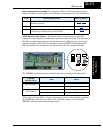
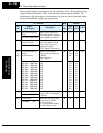
Code Frequency Source Refer to page(s)...
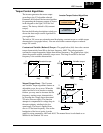
00 Keypad potentiometer - The range of rotation of the knob
matches the range defined by B082 (Start frequency adjust-
ment) to A004 (Maximum frequency setting)
2–23
01 Control terminal - The active analog input signal on analog
terminals [O] or [OI] sets the output frequency
4–51, 3–14, 3–52
02 Function F001 setting - The value in F001 is a constant, used
for the output frequency
3–9
03 ModBus network input - The network has a dedicated
register for inverter output frequency
B–19
10 Calculate function output - The Calculate function has user-
selectable analog input sources (A and B). The output can be
the sum, difference, or product (+, –, x) of the two outputs.
3–29