


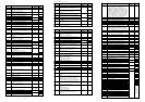
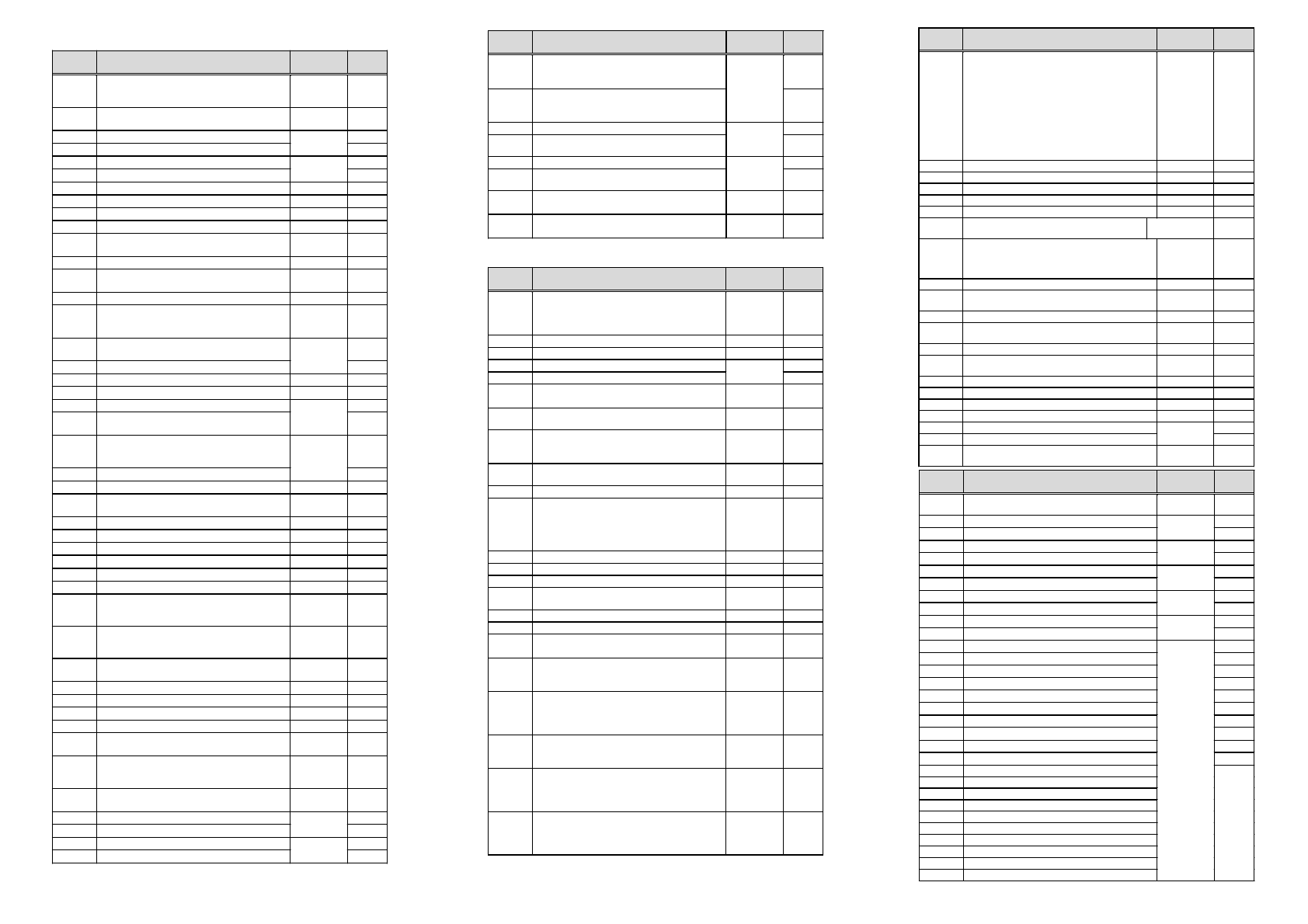
Display Function
Standard
Setting
Set
Value
A 01
Frequency Source setting
00-Potentiometer 01-Terminal O/OI
02-Functions
F 01
/
A 20
01
A 02
Run command source setting
01-Terminal FW/RV 02-RUN key
01
A 03
Base frequency setting
A203
Base frequency setting (2. setting)
50.0
A 04
Maximum frequency setting
A204
Maximum frequency setting (2. setting)
50.0
A 11
External frequency setting start point 0
A 12
External frequency setting end point 0
A 13
External frequency setting start point bias (in %) 0
A 14
External frequency setting end point bias (in %) 100
A 15
External frequency start pattern setting
00-Per
A11
and
A13
01-0Hz
01
A 16
Time constant of the filter for analog inputs 8
A 20 –
A 35
Multispeed frequency setting All are
0.0Hz
A 38
Jog frequency setting 1.0
A 39
Jog stop mode
00-Freerun 01-Deceleration
02-DC brake
00
A 41
Torque boost selection method
00-Manual 01-Automatic
A241
Torque boost selection method (2.
setting)
00
A 42
Value of manual torque boost setting 11
A242
Value of manual torque boost setting (2. setting) 11
A 43
Manual torque boost frequency adjustment (in %)
A243
Manual tor
q
ue boost fre
q
uenc
y
ad
j
ustment (in %)
(2. setting)
10.0
A 44
V/F characteristic setting
00-Constant torque
01-Variable torque 02-SLV
A244
V/F characteristic setting (2. setting)
02
A 45
V-Gain setting (in %) 100
A 51
Selection of DC braking operation
00-NO 01- YES
00
A 52
DC braking frequency setting 0.5
A 53
DC braking waiting time setting 0.0
A 54
DC braking force setting 0
A 55
DC braking time setting 0.0
A 61
Frequency upper limit setting 0.0
A 62
Frequency lower limit setting 0.0
A 63,
A 65,
A 67
Jump frequency setting 0.0
A 64,
A 66,
A 68
Jump frequency width setting 0.5
A 71
Selection of PID control
00-NO 01- YES
00
A 72
P (proportional) gain setting 1.0
A 73
I (integral) gain setting 1.0
A 74
D (differential) gain setting 0.0
A 75
Scale conversion of PID control setting 1.00
A 76
Feedback signal location setting
00-Current 01-Voltage
00
A 81
Selection of AVR function
00-Available 01-Not available
02-Not available at deceleration
02
A 82
Selection of voltage of AVR function for the
motor
FE:230/400
FE:230/460
A 92
Second acceleration time setting
A292
Second acceleration time setting (2. setting)
15.0
A 93
Second deceleration time setting
A293
Second deceleration time setting (2. setting)
15.0
(Table to be continued on next page)
Di
sp
l
ay
Function
Standard
Setting
Set
Value
b 01
Selection of restart mode
00-Alarm 01-0.0Hz restart
02-Motor speed match restart
03-Motor speed match restart /decel to stop
00
b 02
Allowable undervoltage power failure time setting
1.0
b 03
Retry waiting time 1.0
b 12
Level of electronic thermal setting
b212
Level of electronic thermal setting (2. setting)
Rated current
of inverter
b 13
Selection of electronic thermal characteristic
00-Reduced torque 01-Constant torque
01
b213
Selection of electronic thermal characteristic
(2. setting)
01
b 21
Selection of overload limit operation mode
00-NO 01-Accel & constant speed
02-Constant speed
01
b 22
Level of overload limit setting
Rated current
times 1.25
b 23
Rate of deceleration at overload restriction 1.0
b 31
Selection of software lock mode
00-Terminal, no change
01-Terminal, frequency change
02-Keypad, no change
03-Keypad, frequency change
01
b 81
Analog meter adjustment 80
b 82
Start frequency adjustment 0.5
b 83
Carrier frequency setting (kHz) 5.0
b 84
Initialization will 00-Clear trip history
01
-
Restore data & parameters to factory settings
00
b 85
Selection of initialized data
-FE
:0
1 -F
U:0
2
b 86
Frequency converted value setting 1.0
b 87
STOP key active in terminal mode
00-YES 01-NO
00
b 88
Selection of operation when FRS signal is
cancelled
00-Restart at 0 Hz 01-Restart at motor speed
00
b 89
Selection of contents of remote display
01-Frequency 02-Current 03-Direction
04-PID feedback 05-Input terminal status
06-Output terminal status 07-Scaled frequency
01
b 90
Rate of use (in %) of the regenerative braking
resistor during 100 seconds
(00= braking resistor not active)
00
b 91
Deceleration mode selection when using the
STOP key
00-Deceleration stop
01-Free run stop (FRS)
00
b 92
Fan ON/OFF selection
00-Fan is always on
01-Fan is only on if the inverter/motor
is running
00
(Continued from previous page)
Di
sp
l
ay
Function
Standard
Setting
Set
Value
A 94
Selection of method to enable second
acceleration/deceleration (acc2/dec2)
00-Terminal 2CH 01-
A 95
/
A 96
A294
Selection of method to enable second
acceleration/deceleration (acc2/dec2)
(2. setting)
00
A 95
Changed frequency from acc1 to acc2 setting
A295
Changed frequency from acc1 to acc2 setting
(2. setting)
0.0
A 96
Changed frequency from dec1 to dec2 setting
A296
Changed frequency from dec1 to dec2 setting
(2. setting)
0.0
A 97
Pattern of acceleration setting
00-Linear 01-S-curve
00
A 98
Pattern of deceleration setting
00-Linear 01-S-curve
00
D
i
splay
Function
Standard
Setting
Set
Value
C 01
Function of input terminal 1
00-FW (Forward run) 01-RV (Reverse run)
02-CF1 (Multispeed 1) 03-Multispeed 2
04
-
Multispd. 3 05
-
Multispd. 4 06
-
JG (Jogging)
07
-
DB (Ext. DC braking) 08
-
SET (use 2. setting)
09
-
2CH(2. stage accel/decel) 11
-
FRS (Free run
mode) 12
-
EXT (Extern. trip) 13
-
USP
-
function
15
-
SFT (Software lock) 16
-
AT (Analog input
type) 18
-
RS (Reset) 19
-
PTC (only for termi
-
nal 5) 27-UP (remote control acceleration)
28-DWN (remote control deceleration)
00
C 02
Function of input terminal 2 (See
C
01
)01
C 03
Function of input terminal 3 (See
C
01
)
-
FE:02
-
FU:16
C 04
Function of input terminal 4 (See
C
01
)
-
FE:03
-
FU:13
C 05
Function of input terminal 5 (See
C
01
)
-
FE:18
-
FU:09
C 06
Function of input terminal 6 (See
C
01
)
-
FE:09
-
FU:18
C
11 –
C 16
Polarity input of terminal 1-6
00-Normally open 01-Normally closed
00 /
C
14
only
:
-FE:00 -FU:01
C 21
Function of output terminal 11
00-RUN-signal 01-FA1 (frequency constant)
02
-
FA2 (Frequency at set point) 03
-
OL (Over
-
load) 04-OD (PID deviating) 05-AL (Alarm)
01
C 22
Function of output terminal 12 (See
C
21
)00
C 23
Function of FM terminal 00-Analog frequency
01-Analog current 02-Digital frequency
00
C 24
Function of alarm terminal (See
C
21
)05
C 31
Polarity of terminal 11
00-Normally open 01-Normally closed
01
C 32
Polarity of terminal 12 (See
C
31
)01
C 33
Polarity of terminal AL0/AL1
00-Normally open 01-Normally closed
01
C 41
Level of overload signal setting
Rated current
C 42
Arrival frequency setting for acceleration 0.0
C 43
Arrival frequency setting for deceleration 0.0
C 44
Level of PID deviation signal setting 3.0
C 81
Frequency command adjustment (terminal O)
C 82
Frequency command adjustment (terminal OI)
C 91 –
C 95
For further use, do not change.
--
D
i
splay
Function
Standard
Setting
Set
Value
H 01
Autotuning mode: 00-Autotuning off
01-Autotuning on 02-Autotuning/static
00
H 02
Motor data: 00-Standard Hitachi 01-Auto
H202
Motor data (2.
setting)
00
H 03
Motor capacity
H203
Motor capacity (2.
setting)
Depending
on model
H 04
Number of motor poles
H204
Number of motor poles (2. setting)
4
H 05
Motor constant Kp
H205
Motor constant Kp (2. setting)
20
H 06
Motor stabilization constant
H206
Motor stabilization constant. (2.
setting)
100
H 20
Motor constant R1
H220
Motor constant R1 (2. setting)
H 21
Motor constant R2
H221
Motor constant R2 (2. setting)
H 22
Motor constant L
H222
Motor constant L (2. setting)
H 23
Motor constant Io
H223
Motor constant Io (2. setting)
H 24
Motor constant J
H224
Motor constant J (2. setting)
H 30
Motor constant R1 Autotuning
H230
Motor constant R1 Autotuning (2. setting)
H 31
Motor constant R2 Autotuning
H231
Motor constant R2 Autotuning (2. setting)
H 32
Motor constant L Autotuning
H232
Motor constant L Autotuning (2. setting)
H 33
Motor constant Io Autotuning
H233
Motor constant Io Autotuning (2. setting)
H 34
Motor constant J Autotuning
H234
Motor constant J Autotuning (2. setting)
Depending
on model
These
para-
meters
must not
be
chan
g
ed!
6 7 8