


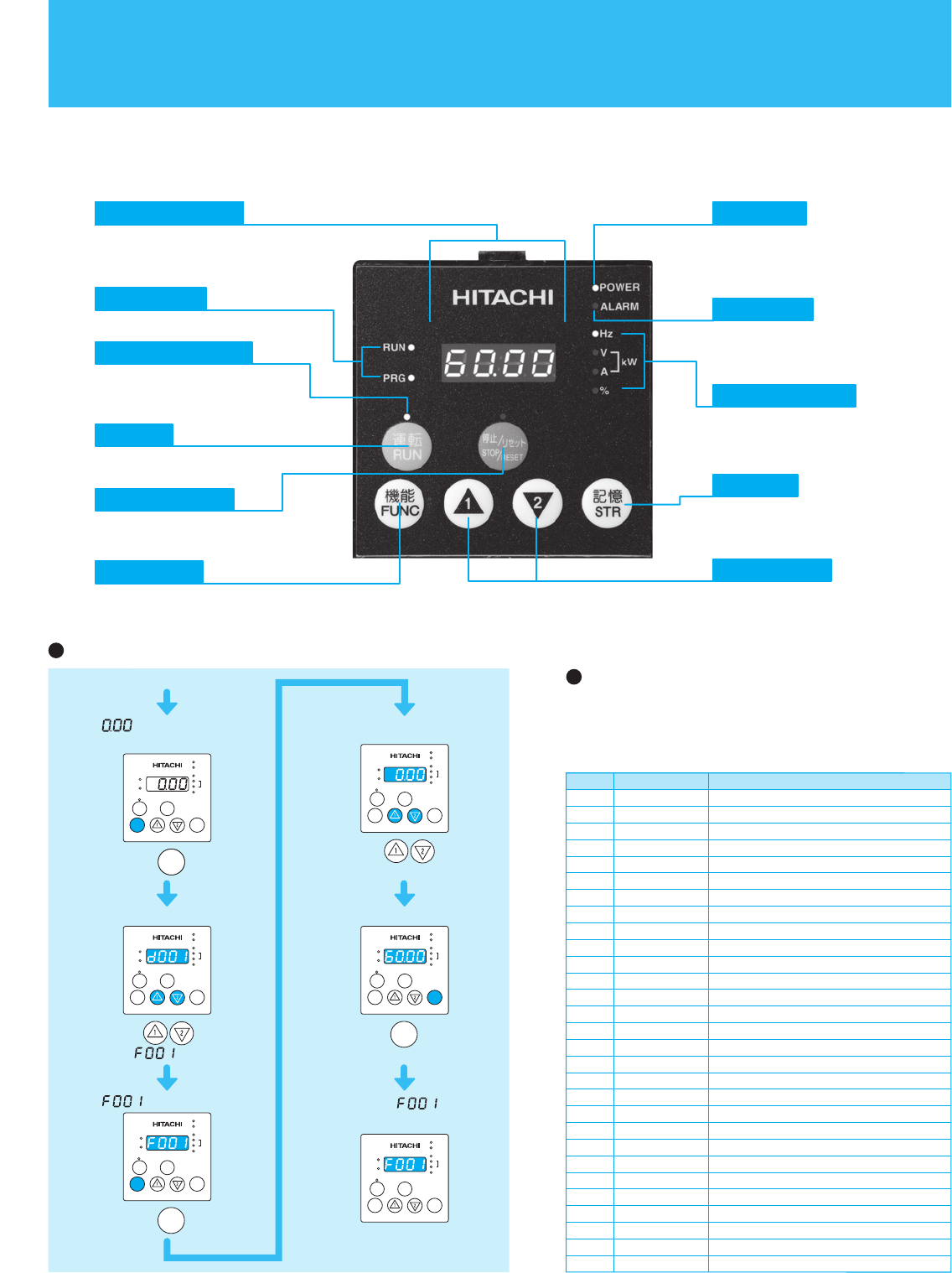
OPERATION and PROGRAMMING
Press
until appears.
1 or the value previously
monitored is displayed.
2 Function code appears.
3 appears.
Power on
Press key.
Press key.
FUNC
FUNC
4 Preset value is displayed.
5 Newly set value is displayed.
6 Returns to and
the setting is complete.
Press
to set desired value.
Press key
to store the value.
To run the motor, go back to
monitor mode or basic setting mode.
STR
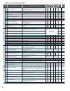
The contents of a basic mode display.
Setting the output frequency
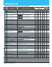
No.
1
2
3
4
5
6
7
8
9
10
11
12
13
14
15
16
17
18
19
20
21
22
23
24
25
26
27
28
29
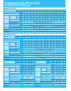
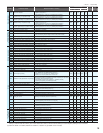
Display code
d001 to d104
F001
F002
F003
F004
A001
A002
A003
A004
A005
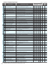
A020
A021
A022
A023
A044
A045
A085
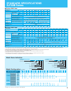
b001
b002
b008
b011
b037
b083
b084
b130
b131
C021
C022
C036
Item
Monitor display
Output frequency setting
Acceleration (1) time setting
Deceleration (1) time setting
Operation direction setting
Frequency source setting
Run command source setting
Base frequency setting
Maximum frequency setting
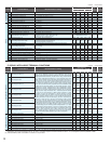
[AT] selection
Multi-speed frequency setting
Multi-speed 1 setting
Multi-speed 2 setting
Multi-speed 3 setting
1st control method
V/f gain setting
Operation mode selection
Selection of restart mode
Allowable under-voltage power failure time
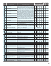
Retry-after-trip selection
Retry wait time after trip
Function code display restriction
Carrier frequency setting
Initialization mode selection
Selection of overvoltage suppression function
Setting of overvoltage suppression level
Setting of intelligent output terminal 11
Setting of intelligent output terminal 12
Alarm relay active state
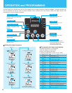
SJ700/SJ700D and SJ700B Series can be easily operated with the digital operator provided as standard. The digital operator can
also be detached and can be used for remote mounted control. Operator with copy function (WOP) and digital operator with
potentiometer are also available as options.
Shows drive status.
Press to run the motor.
Press to stop the drive or
reset an alarm.
Lights when the power input
to the drive is ON.
Indicates the unit associated
with the parameter display.
Press to write the new value
to the EEPROM.
Press up or down to sequence
through parameters and functions
shown on the display, and
increment/decrement values.
Press to set or monitor a
parameter value.
Parameter Display Power LED
Display Unit LEDs
Lights to indicate that the
inverter has tripped.
ALARM LED
Store Key
Up/Down Keys
Monitor LEDs
Lights up when the inverter
is ready to respond to the
RUN key.
RUN key enable LED
RUN Key
STOP/RESET Key
Function Key
Displays frequency, motor current,
rotational speed of the motor, and
an alarm code.
If a desired parameter is not displayed,
check the setting of function "b037"
(function code display restriction).
To display all parameters, specify "00" for "b037".
13