


(*1): Reset operation is acceptable 10 seconds after the trip. (185kW and over :90 seconds) *2): Check the parameters when EEPROM error occurs. (*3): The inverter will not accept reset commands input via the RS terminal
or entered by the STOP/RESET key. Therefore, turn off the inverter power. (*4): The inverter will not accept the reset command entered from the digital operator. Therefore, reset the inverter by turning on the RS terminal.
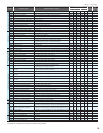
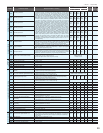
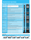
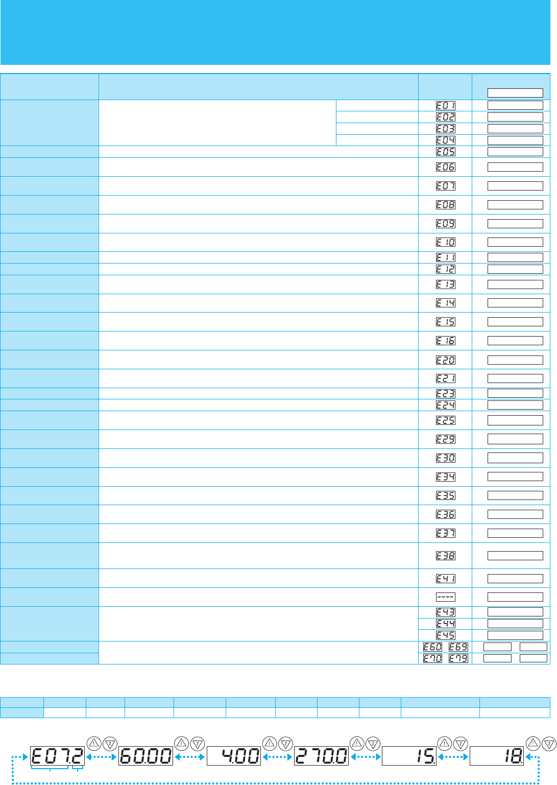
How to access the details about the present fault
Status Display
Name
Display
on digital
operator
Display on remote
operator/copy unit
Cause (s)
Over-current protection
Overload protection (*1)
Braking resistor
overload protection
Over-voltage protection
EEPROM error (*2)
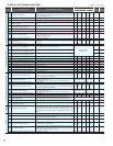
Under-voltage error
CT (Current transformer) error
CPU error
External trip
USP error
Ground fault
Input over-voltage protection
Instantaneous power failure
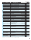
Inverter thermal trip
Gate array error
Phase loss input protection
IGBT error
Thermistor error
Braking error
Out of operation due
to under-voltage
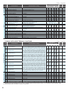
Expansion card 1 connection error
Expansion card 2 connection error
Communication error has occurred between CPU and gate array.
One of three lines of 3-phase power supply is missing.
An error has been detected in an expansion card or at its connecting terminals.
While at constant speed
During deceleration
During acceleration
Others
When the built-in EEPROM memory has problems due to noise or excessive temperature, the inverter trips
and turns off its output.
When a signal to an intelligent input terminal configured as EXT has occurred, the inverter trips and turns off its output.
An error occurs when power is cycled while the inverter is in RUN mode if the Unattended Start Protection
(USP) is enabled. The inverter trips and does not go into RUN mode until the error is cleared.
When the input voltage is higher than the specified value, it is detected 60 seconds after power-up and the
inverter trips and turns of its output.
When power is cut for more than 15ms, the inverter trips and turns off its output. If power failure continues,
the error will be cleared. The inverter restarts if it is in RUN mode when power is cycled.
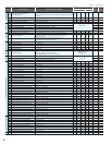
Temperature error due to low
cooling-fan speed
The inverter will display the error code shown on the right if the lowering of cooling-fan speed is detected at
the occurrence of the temperature error described below.
The inverter turns off its output when it can not detect whether the braking is ON or OFF within waiting time
set at b024 after it has released the brake. (When braking is enabled at b120)
When the DC bus voltage exceeds a threshold, due to regenerative energy from the motor, the inverter trips
and turns off its output.
When a motor overload is detected by the electronic thermal function, the inverter trips and turns off its output.
The inverter output was short-circuited, or the motor shaft is locked or has a
heavy load. These conditions cause excessive current for the inverter, so the
inverter output is turned off.
Easy sequence function Error
When the regenerative braking resistor exceeds the usage time allowance or an over-voltage caused by the
stop of the BRD function is detected, the inverter trips and turns off its output.
A decrease of internal DC bus voltage below a threshold results in a control circuit fault. This condition can
also generate excessive motor heat or cause low torque. The inverter trips and turns off its output.
If a strong source of electrical interference is close to the inverter or abnormal operations occur in the
built-in CT, the inverter trips and turns off its output.
The inverter is protected by the detection of ground faults between the inverter output and the motor during
power-up tests. This feature protects the inverter only.
When the inverter internal temperature is higher than the specified value, the thermal sensor in the inverter
module detects the higher temperature of the power devices and trips, turning off the inverter output.
When an instantaneous over-current has occurred, the inverter trips and turns off its output to protect main
circuit element.
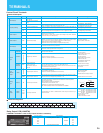
Cooling-fan speed drop signal
If the rotation speed of the internal cooling fan decreases so that the cooling effect decreases,inverter
output turns OFF for protection. (available only for SJ700 1850-4000)
Main circuit error (*3)
The inverter will trip if the gate array cannot confirm the on/off state of IGBT because of a malfunction due
to noise or damage to the main circuit element.
When the thermistor inside the motor detects temperature higher than the specified value, the inverter trips
and turns off its output.
Emergency stop (*4)
If the EMR signal (on three terminals) is turned on when the slide switch (SW1) on the logic board is set to
ON, the inverter hardware will shut off the inverter output and display the error code shown on the right.
Modbus communication error
If timeout occurs because of line disconnection during the communication in Modbus-RTU mode, the inverter
will display the error code shown on the right. (The inverter will trip according to the setting of "C076".)
Low-speed overload protection
If overload occurs during the motor operation at a very low speed at 0.2 Hz or less, the electronic thermal protection
circuit in the inverter will detect the overload and shut off the inverter output. (2nd electronic thermal control)
(Note that a high frequency may be recorded as the error history data.)
Due to insufficient voltage, the inverter has turned off its output and been trying to
restart. If it fails to restart, it goes into the under-voltage error.
When a malfunction in the built-in CPU has occurred, the inverter trips and turns off its output.
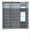
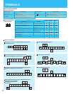
Error indications by protective functions with the easy sequence function used.
Status at trip pointError code
Output frequency
at trip point
Motor current
at trip point
Voltage between
P (+) and N ) at trip point
Cumulative inverter
RUN time at trip point
Cumulative power-on
time at trip point
OC.Drive
ERR1****
OC.Decel
OC.Accel
Over.C
Over.L
OL.BRD
Over.V
EEPROM
Under.V
CT
CPU
EXTERNAL
USP
GND.Flt.
OV.SRC
Inst.P-F
OH FIN
GA.COM
PH.Fail
IGBT
Fan. Slow
TH
BRAKE
UV.WAIT
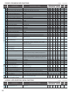
OP1-0 OP1-9
OP2-0 OP2-9
PRG.CMD
PRG.NST
PRG.ERR1
OH.stFAN
Main.Cir
Phase loss output protection
(SJ700D only)
When the phase loss output protection has been enabled (b141=01), the inverter will trip to avoid damage if
a phase loss output is detected.
O.PH.Fail
EMR
NET.ERR
OL-LowSP
Code
Description
Reset
0
Stop
1
Deceleration
2
Constant Speed
3
Acceleration
4
f0 Stop
5
Starting
6
DB
7
Overload Restriction
8
Forcible or servo-on
9
PROTECTIVE FUNCTIONS
24