


Unbalance factor of voltage =
V
RS
-(V
RS
+V
ST
+V
TR
)/3
(V
RS
+V
ST
+V
TR
)/3
Max. line voltage (min.) - Mean line voltage
Mean line voltage
x
100
=
x
100 =
x
100 =1.5(%)
205-202
202
Installation location and operating environment
Avoid installation in areas of high temperature, excessive humidity, or where moisture can easily collect, as well as areas that are dusty, subject to
corrosive gasses, mist of liquid for grinding, or salt. Install the inverter away from direct sunlight in a well-ventilated room that is free of vibration. The
inverter can be operated in the ambient temperature range from SJ700/SJ700D (CT): -10 to 50˚C, SJ700D (VT): -10 to 40˚C, SJ700B: -10 to 45˚C.
(Carrier frequency and output current must be reduced in the range of 40 to 50˚C.)
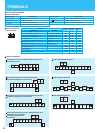
In the following examples involving a general-purpose inverter, a large peak current flows on the main power supply side, and is
able to destroy the converter module. Where such situations are foreseen or the connected equipment must be highly reliable,
install an AC reactor between the power supply and the inverter. Also, where influence of indirect lightning strike is possible,
install a lightning conductor.
(A) The unbalance factor of the power supply is 3% or higher. (Note)
(B) The power supply capacity is at least 10 times greater than the inverter capacity (the power supply capacity is 500 kVA or more).
(C) Abrupt power supply changes are expected.
Examples:
(1) Several inverters are interconnected with a short bus.
(2) A thyristor converter and an inverter are interconnected with a short bus.
(3) An installed phase advance capacitor opens and closes.
In cases (A), (B) and (C), it is recommended to install an AC reactor on the main power supply side.
Note: Example calculation with V
RS
= 205V, V
ST
= 201V, V
TR
= 200V
V
RS
: R-S line voltage, V
ST
: S-T line voltage, V
TR
: T-R line voltage
An inverter run by a private power generator may overheat the generator or suffer from a deformed output voltage waveform of the
generator. Generally, the generator capacity should be five times that of the inverter (kVA) in a PWM control system, or six times
greater in a PAM control system.
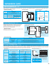
Main power supply
Installation of an
AC reactor on the
input side
Using a private power
generator
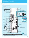
(1) Be sure to connect main power wires with R (L1), S (L2), and T (L3) terminals (input) and motor wires to U (T1), V (T2), and W
(T3) terminals (output). (Incorrect connection will cause an immediate failure.)
(2) Be sure to provide a grounding connection with the ground terminal ( ).
When an electromagnetic contactor is installed between the inverter and the motor, do not perform on-off switching during running
operation.
When used with standard applicable output motors (standard three-phase squirrel-cage four-pole motors), the SJ700/SJ700D/
SJ700B Series does not need a thermal relay for motor protection due to the internal electronic protective circuit. A thermal relay,
however, should be used:
• during continuous running outside a range of 30 to 60 Hz.
• for motors exceeding the range of electronic thermal adjustment (rated current).
• when several motors are driven by the same inverter; install a thermal relay for each motor.
• The RC value of the thermal relay should be more than 1.1 times the rated current of the motor. If the wiring length is 10 m or
more, the thermal relay tends to turn off readily. In this case, provide an AC reactor on the output side or use a current sensor.
Install a circuit breaker on the main power input side to protect inverter wiring and ensure personal safety. Choose an inverter-
compatible circuit breaker. The conventional type may malfunction due to harmonics from the inverter. For more information, consult
the circuit breaker manufacturer.
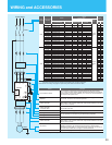
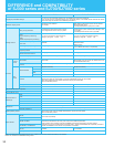
Notes on Peripheral Equipment Selection
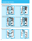
Wiring connections
Installing a circuit breaker
The wiring distance between the inverter and the remote operator panel should be 20 meters or less. Shielded cable should be used
on thewiring. Beware of voltage drops on main circuit wires. (A large voltage drop reduces torque.)
Wiring distance
If the earth leakage relay (or earth leakage breaker) is used, it should have a sensitivity level of 15 mA or more (per inverter).
Earth leakage relay
Do not use a capacitor for power factor improvement between the inverter and the motor because the high-frequency components
of the inverter output may overheat or damage the capacitor.
Phase advance capacitor
Electromagnetic
contactor
Wiring
between
inverter and
motor
Thermal relay
High-frequency Noise and Leakage Current
(1) High-frequency components are included in the input/output of the inverter main circuit, and they may cause interference in a transmitter,
radio, or sensor if used near the inverter. The interference can be minimized by attaching noise filters (option) in the inverter circuitry.
(2) The switching action of an inverter causes an increase in leakage current. Be sure to ground the inverter and the motor.
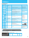
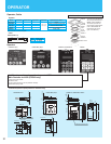
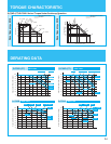
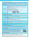
Lifetime of Primary Parts
Because a DC bus capacitor deteriorates as it undergoes internal chemical reaction, it should normally be replaced
every five years. Be aware, however, that its life expectancy is considerably shorter when the inverter is subjected
to such adverse factors as high temperatures or heavy loads exceeding the rated current of the inverter. The
approximate lifetime of the capacitor is as shown in the figure at the right when it is used 12 hours daily (according
to the
"
Instructions for Periodic Inspection of General-Purpose Inverter
"
(JEMA).) Also, such moving parts as a
cooling fan should be replaced. Maintenance inspection and parts replacement must beperformed by only specified
trained personnel. Please plan to replace new inverter depends on the load, ambient condition in advance.
$PELHQWWHPSHUDWXUHÝ&
&DSDFLWRUOLIHWLPH\HDUV
6-6-'&7
SJ700B
6-'97
50
40
30
2.5 5 10
Precaution for Correct Usage
• Before use, be sure to read through the Instruction Manual to insure proper use of the inverter.
• Note that the inverter requires electrical wiring; a trained specialist should carry out the wiring.
• The inverter in this catalog is designed for general industrial applications. For special applications in fields such as aircraft, outer space,
nuclear power, electrical power, transport vehicles, clinics, and underwater equipment, please consult with us in advance.
•
For application in a facility where human life is involved or serious injury may occur, make sure to provide safety devices to avoid any accident.
•
The inverter is intended for use with a three-phase AC motor. For use with a load other than this, please consult with us.
Information in this brochure is subject to change without notice.
38