


= Allowed
= Not permitted
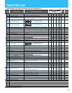
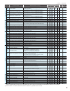
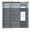
Code Function Name Monitored data or setting
Default Setting
Setting
during
operation
(allowed or not)
Change
during
operation
(allowed or not)
SJ700/SJ700D(CTmode)
SJ700B
-FE -FU -F -F -FU
Torque limitation
b040
Torque limit selection
00 (quadrant-specifi c setting), 01 (switching by terminal), 02 (analog input),
03 (option 1),04 (option 2)
00 00 00 00 00
b041
Torque limit (1)
(Forward-driving in 4-quadrant mode)
SJ700/SJ700D (CT): 0. to 200. (%), no (disabling torque limitation)
< 75kW and over:0. to 180.>
SJ700D (VT)/SJ700B: 0. to 150. (%), no (disabling torque limitation)
150. 150. 150. 150. 120.
b042
Torque limit (2)
(Reverse-regenerating in 4-quadrant mode)
SJ700/SJ700D (CT): 0. to 200. (%), no (disabling torque limitation)
< 75kW and over:0. to 180.>
SJ700D (VT)/SJ700B: 0. to 150. (%), no (disabling torque limitation)
150. 150. 150. 150. 120.
b043
Torque limit (3)
(Reverse-driving in 4-quadrant mode)
SJ700/SJ700D (CT): 0. to 200. (%), no (disabling torque limitation)
< 75kW and over:0. to 180.>
SJ700D (VT)/SJ700B: 0. to 150. (%), no (disabling torque limitation)
150. 150. 150. 150. 120.
b044
Torque limit (4)
(Forward-regenerating in 4-quadrant mode)
SJ700/SJ700D (CT): 0. to 200. (%), no (disabling torque limitation)
< 75kW and over:0. to 180.>
SJ700D (VT)/SJ700B: 0. to 150. (%), no (disabling torque limitation)
150. 150. 150. 150. 120.
b045
Torque limit LADSTOP enable
00 (disabling), 01 (enabling)
00 00 00 00 00
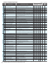
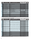
Non-stop operation at
momentary power failure
b046
Reverse RUN protection enable
00 (disabling), 01 (enabling)
00 00 00 00 01
b049
CT/VT selection (SJ700D only)
00 (CT : Constant torque), 01 (VT : Variable torque)
00 00 00
b050
Controlled deceleration and stop on power loss
00 (disabling), 01 (nonstop deceleration to stop), 02 (DC voltage constant
control, with resume), 03 (DC voltage constant control, without resure)
00 00 00 00 00
b051
DC bus voltage trigger level during power loss
0.0 to 999.9, 1000. (V)
220.0/440.0 220.0/440.0 220.0/440.0 220.0/440.0 220.0/440.0
b052
Over-voltage threshold during power loss
0.0 to 999.9, 1000. (V)
360.0/720.0 360.0/720.0 360.0/720.0 360.0/720.0 360.0/720.0
b053
Deceleration time setting during power loss
0.01 to 99.99, 100.0 to 999.9, 1000. to 3600. (s)
1.00 1.00 1.00 1.00 1.00
b054
Initial output frequency decrease during power loss
0.00 to 10.00 (Hz)
0.00 0.00 0.00 0.00 0.00
b055
Proportional gain setting for nonstop operation at power loss
0.00 to 2.55
0.20 0.20 0.20 0.20 0.20
b056
Integral time setting for nonstop operation at power loss
0.0 to 9.999 /10.00 to 65.55
0.100 0.100 0.100 0.100 0.100
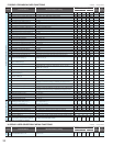
Window comparator
b060
Maximum-limit level of window comparators O
0. to 100. (lower limit : b061 + b062*2) (%)
100 100 100 100 100
b061
Minimum-limit level of window comparators O
0. to 100. (lower limit : b060 - b062*2) (%)
00000
b062
Hysteresis width of window comparators O
0. to 10. (lower limit : b061 - b062 / 2) (%)
00000
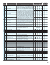
b063
Maximum-limit level of window comparators OI
0. to 100. (lower limit : b064 + b066*2) (%)
100 100 100 100 100
b064
Minimum-limit level of window comparators OI
0. to 100. (lower limit : b063 - b066*2) (%)
00000
b065
Hysteresis width of window comparators OI
0. to 10. (lower limit : b063 - b064 / 2) (%)
00000
b066
Maximum-limit level of window comparators OI
-100. to 100. (lower limit : b067 + b068*2) (%)
100 100 100 100 100
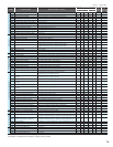
b067
Minimum-limit level of window comparators O/OI/O2
-100. to 100. (lower limit : b066 - b068*2) (%)
-100 -100 -100 -100 -100
b068
Hysteresis width of window comparators O/OI/O2
0. to 10. (lower limit : b066 - b067 / 2) (%)
00000
b070
Operation level at O disconnection
0 to 100 (%) or "no" (ignore)
255(no) 255(no) 255(no) 255(no) 255(no)
b071
Operation level at OI disconnection
0 to 100 (%) or "no" (ignore)
255(no) 255(no) 255(no) 255(no) 255(no)
b072
Operation level at O2 disconnection
0 to 100 (%) or "no" (ignore)
127(no) 127(no) 127(no) 127(no) 127(no)
Others
b078
Cumulative input power data clearance
Clearance by setting "01" and pressing the STR key
00 00 00 00 00
b079
Cumulative input power display gain setting
1. to 1000.
1. 1. 1. 1. 1.
b082
Start frequency adjustment
0.10 to 9.99 (Hz)
0.50 0.50 0.50 0.50 0.50
b083
Carrier frequency setting
SJ700/SJ700D (CT): 0.5 to 15.0 (kHz)
<75 to 132kW:0.5 to 10.0/185kW and over:0.5 to 3.0>
SJ700D (VT): 0.5 to 12.0 (kHz) <75 to 132kW:0.5 to 8.0.>
SJ700B: 0.5 to 12.0 (kHz) <90kW and over:0.5 to 8.0>
5.0(*2) 5.0(*2) 5.0(*2) 3.0(*1) 3.0(*1)
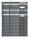
b084
Initialization mode (parameters or trip history)
SJ700D: 00 (disabling), 01 (cleaning the trip history), 02 (initializing the data), 03
(cleaning the trip history and initializing the data), 04 (cleaning the trip history
and initializing the data and EzSQ program)
SJ700/SJ700B: 00 (clearing the trip history), 01 (initializing the data),
02 (clearing the trip history and initializing the data)
00 00 00 00 00
b085
Country code for initialization
00 (Japan), 01 (EU), 02 (U.S.A.)
01 02 00 01 02
b086
Frequency scaling conversion factor
0.1 to 99.9
1.0 1.0 1.0 1.0 1.0
b087
STOP key enable
00 (enabling), 01 (disabling), 02 (disabling only the function to stop)
00 00 00 00 00
b088
Restart mode after FRS
00 (starting with 0 Hz), 01 (starting with matching frequency),
02 (starting with active matching frequency)
00 00 00 00 00
b089
Automatic carrier frequency reduction
00: invalid, 01: valid
00 00 00 00 00
b090
Dynamic braking usage ratio
0.0 to 100.0 (%)
0.0 0.0 0.0 0.0 0.0
b091
Stop mode selection
00 (deceleration until stop), 01 (free-run stop)
00 00 00 00 00
b092
Cooling fan control
00 (always operating the fan), 01 (operating the fan only during inverter operation
[including 5 minutes after power-on and power-off ])
00 00 00 00 01
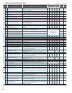
b095
Dynamic braking control
00 (disabling), 01 (enabling [disabling while the motor is topped]),
02 (enabling [enabling also while the motor is topped])
00 00 00 00 01
b096
Dynamic braking activation level
330 to 380, 660 to 760 (V)
360/720 360/720 360/720 360/720 360/720
b098
Thermistor for thermal protection control
00 (disabling the thermistor), 01 (enabling the thermistor with PTC),
02 (enabling the thermistor with NTC)
00 00 00 00 00
b099
Thermal protection level setting
0. to 9999. (Ω)
3000. 3000. 3000. 3000. 3000.
Free setting of V/f
characteristic
b100
Free-setting V/f frequency (1)
0. to "free-setting V/f frequency (2)" (Hz)
0. 0. 0. 0. 0.
b101
Free-setting V/f voltage (1)
0.0 to 800.0 (V)
0.0 0.0 0.0 0.0 0.0
b102
Free-setting V/f frequency (2)
0. to "free-setting V/f frequency (3)" (Hz)
0. 0. 0. 0. 0.
b103
Free-setting V/f voltage (2)
0.0 to 800.0 (V)
0.0 0.0 0.0 0.0 0.0
b104
Free-setting V/f frequency (3)
0. to "free-setting V/f frequency (4)" (Hz)
0. 0. 0. 0. 0.
b105
Free-setting V/f voltage (3)
0.0 to 800.0 (V)
0.0 0.0 0.0 0.0 0.0
b106
Free-setting V/f frequency (4)
0. to "free-setting V/f frequency (5)" (Hz)
0. 0. 0. 0. 0.
b107
Free-setting V/f voltage (4)
0.0 to 800.0 (V)
0.0 0.0 0.0 0.0 0.0
(
*1) “Over current protection” , ” Overload restriction” , “Over current limiting” and “Electronic thermal protection” might operate from the set value when “Carrier frequency
setting” is used with less than 2kHz by a low value. Please set to 2kHz or more and use the setting of “Carrier frequency setting” for such a situation.
(*2) 750HF to 1320HF: 3.0 1850HF, 2200HF and 3150HF:2.1, 4000HF:1.9 (*3) 4000HF: 0.0 to 120.0 (Hz
)
18